Forage grass cutting equipment

A kind of equipment and section cutting technology, which is applied in the direction of cutting equipment, agricultural machinery and implements, applications, etc., and can solve the problems of low degree of automation and uneven section cutting

Inactive Publication Date: 2019-10-15
徐龙江
View PDF9 Cites 0 Cited by
  • Summary
  • Abstract
  • Description
  • Claims
  • Application Information

AI Technical Summary

Problems solved by technology

[0002] The feeding of livestock often needs to cut the forage grass. The traditional cutting equipment has the problems of low automation and uneven cutting. The purpose of this invention is to solve these problems

Method used


Image

  • Forage grass cutting equipment
  • Forage grass cutting equipment
  • Forage grass cutting equipment

Examples


specific Embodiment approach 1

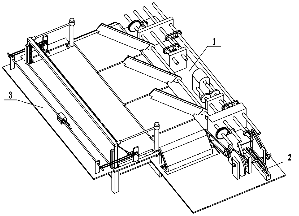
[0029] Combine below Figure 1-15 Describe this embodiment, a kind of forage cutting equipment, including guillotine cutting assembly 1, conveying device 2 and feeding assembly 3, described guillotine cutting assembly 1 is connected with conveying device 2, and feeding assembly 3 is connected with conveying device Device 2 is connected.

specific Embodiment approach 2

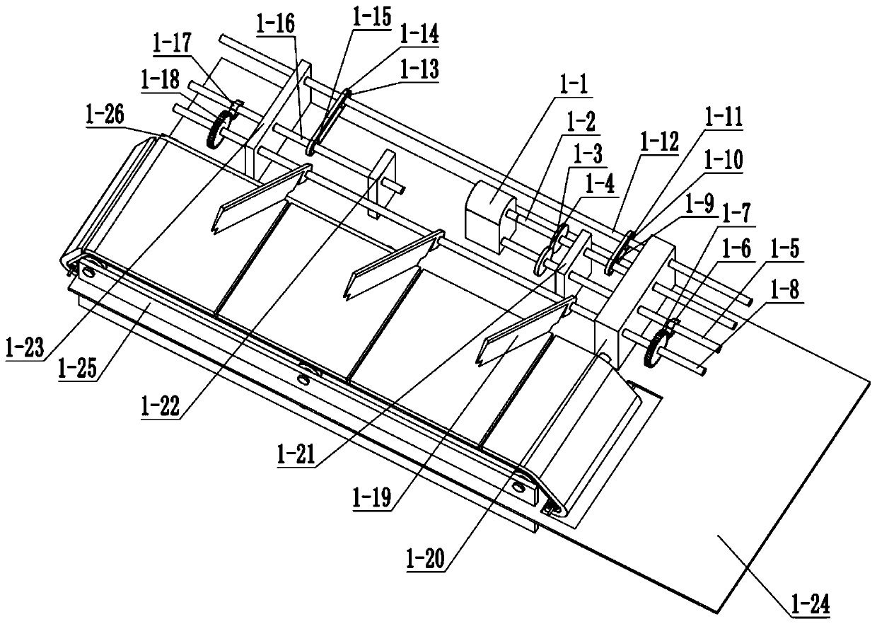
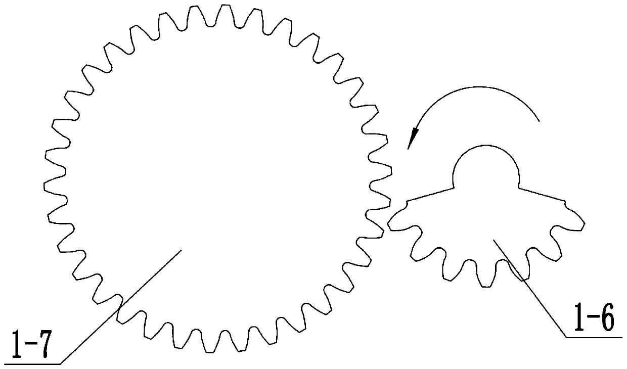
[0031] Combine below Figure 1-15 This embodiment will be described. This embodiment will further explain Embodiment 1. The guillotine assembly 1 includes a guillotine motor 1-1, a guillotine motor shaft 1-2, a gear I1-3, and a gear II1-4. , gear Ⅱ shaft 1-5, half gear Ⅰ 1-6, cutting gear Ⅰ 1-7, cutting gear Ⅰ shaft 1-8, cutting motor shaft sprocket 1-9, chain Ⅰ 1-10, sprocket Ⅰ 1-11 , sprocket Ⅰ shaft 1-12, sprocket Ⅱ 1-13, chain Ⅱ 1-14, sprocket Ⅲ 1-15, sprocket Ⅲ shaft 1-16, half gear Ⅱ 1-17, guillotine cutting gear Ⅱ 1-18, guillotine 1- 19. Support Ⅰ1-20, support Ⅱ1-21, support Ⅲ1-22, support Ⅳ1-23, guillotine cutting base plate 1-24, support Ⅴ1-25 and support Ⅵ1-26, guillotine cutting motor 1-1 and guillotine cutting motor shaft 1-2 phase connection, the guillotine motor 1-1 is connected with the guillotine bottom plate 1-24, the guillotine motor shaft 1-2 is connected with the gear I1-3, the gear I1-3 is meshed with the gear II1-4, and the gear II1-4 is connected with ...

specific Embodiment approach 3

[0033] Combine below Figure 1-15 Describe this embodiment, this embodiment will further explain the first embodiment, the transmission device 2 includes a ratchet shaft bracket 2-1, a gear IV shaft bracket 2-2, a guillotine cutting motor shaft bevel gear 2-3, and a bevel gear I2 -4. Bevel gear I axis 2-5, sprocket IV 2-6, chain III 2-7, sprocket V2-8, sprocket V axis 2-9, half gear III 2-10, gear frame 2-11, gear frame Slide rail 2-12, connecting column 2-13, slide bar 2-14, slide bar slide rail 2-15, rocker I 2-16, rocker shaft 2-17, gear shaft 2-18, gear 2- 19. Ratchet 2-20, ratchet shaft 2-21, gear Ⅲ 2-22, gear Ⅳ 2-23, gear Ⅳ shaft 2-24, sprocket Ⅵ 2-25, chain Ⅳ 2-26, sprocket Ⅶ2-27, sprocket Ⅷ 2 -28, sprocket VIII shaft 2-29, chain V2-30, sprocket bracket 2-31, sprocket bracket shaft 2-32, sprocket IX 2-33, transmission belt 2-34, bevel gear I shaft bracket 2- 35. Sprocket V shaft bracket 2-36 and rocker shaft bracket 2-37, the guillotine motor 1-1 is connected with the...


PUM


Abstract

The invention relates to the forage field, in particular to forage grass cutting equipment. The equipment comprises a cutting assembly, a conveying device and a feeding assembly. Forage grass is oftencut for feeding of livestock, and traditional cutting equipment has problems of low automation degree and non-uniform cutting. The forage grass cutting equipment aims to solve these problems, throughsectional conveying by the conveying device and simultaneous cutting by a cutter, the cutting length of forage grass is consistent, livestock can absorb nutrients of the forage grass more easily, digestion and absorption of the livestock are felicitated, a fixing device of a feeding shovel slowly lowers from top to bottom, the feeding shovel stirs uncut forage grass to a cutting device along a slide rail, two kinds of motion are performed simultaneously, the feeding shovel stirs the forage grass obliquely downwards, the volumes of the forage grass stirred each time are equal, the condition that cutting is not thorough due to the fact the excessive forage grass is fed once is avoided, and the cutting efficiency is improved.

Description

technical field [0001] The invention relates to the field of feed, more specifically to a forage cutting equipment. Background technique [0002] Feeding of livestock often requires guillotine cutting of forage grass. Traditional guillotine cutting equipment has the problems of low automation and uneven cutting. The purpose of the present invention is to solve these problems. Contents of the invention [0003] The purpose of the present invention is achieved through the following technical solutions: [0004] A forage grass cutting device includes a guillotine cutting assembly, a conveying device and a feeding assembly, the guillotine cutting assembly is connected with the conveying device, and the feeding assembly is connected with the conveying device. [0005] As a further optimization of this technical solution, the present invention provides a forage grass cutting equipment, and the guillotine cutting assembly includes a guillotine cutting motor, a guillotine cutting...

Claims


Application Information

Patent Timeline
Patent Type & Authority Applications(China)
IPC IPC(8): A01F29/08A01F29/09
CPCA01F29/08A01F29/09
Inventor 徐龙江
Owner 徐龙江
Why Eureka
Try Eureka