
Deicing tool for electric equipment

A technology for power equipment and tools, which is applied in the field of deicing tools for power equipment, can solve problems such as hand numbness, reduce the work efficiency of deicing personnel, leakage and short circuit, etc., and achieve the effect of facilitating storage, improving user experience, and soft contact mode

Pending Publication Date: 2019-10-15
国网浙江兰溪市供电有限公司 +1
View PDF0 Cites 6 Cited by
  • Summary
  • Abstract
  • Description
  • Claims
  • Application Information

AI Technical Summary

Problems solved by technology

[0002] Large-scale electrical equipment in the outdoor environment will have thick snow in winter rainy and snowy days. In particular, the snow will easily produce hard ice after melting, which not only increases the load on the electrical equipment, but also has the risk of leakage and short circuit , in order to ensure the safe operation of power equipment, the staff need to clear snow and remove ice in time, but the existing deicing tools mainly use percussion tools such as hammers and maces, and their percussion operations are not only easy to damage the shell of power equipment , and the vibration of the deicing knock will be transmitted to the human hand through the hammer handle, and the operator will cause hand numbness when holding the hammer for a long time, which greatly reduces the work efficiency of the deicing personnel in the low temperature environment

Method used


Image

  • Deicing tool for electric equipment
  • Deicing tool for electric equipment
  • Deicing tool for electric equipment

Examples


Embodiment Construction

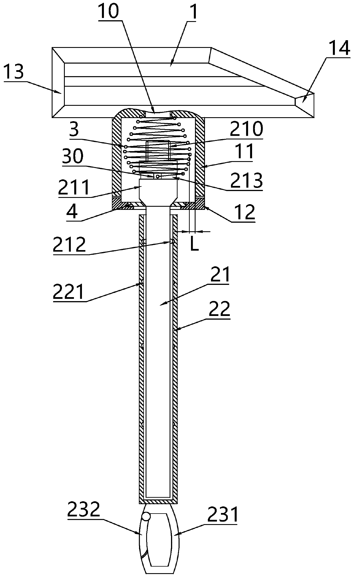
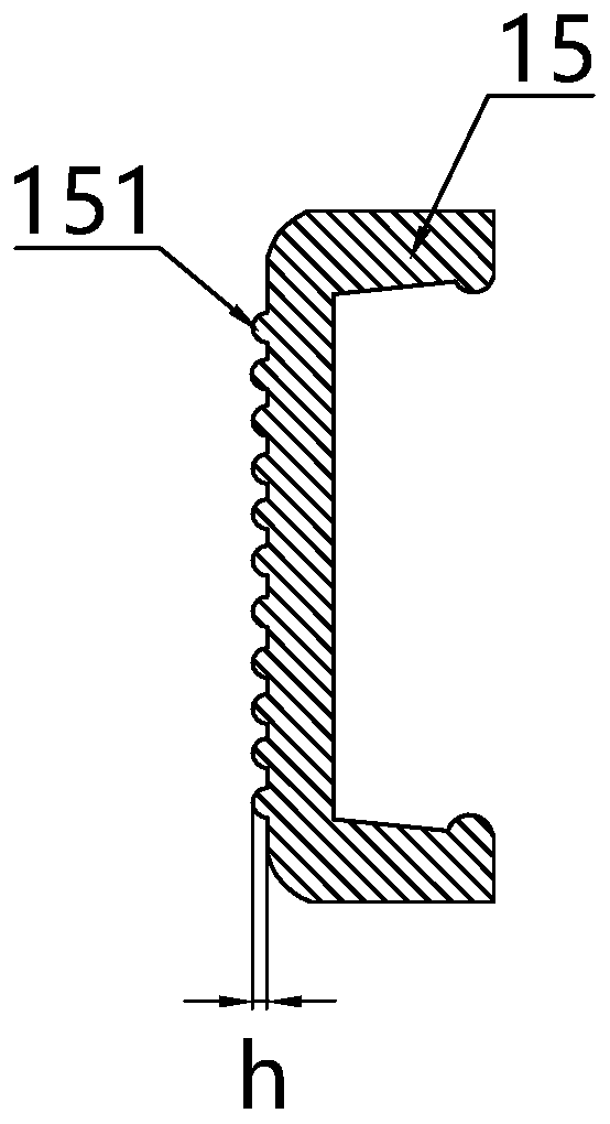
[0019] The invention provides a deicing tool for electric equipment, such as figure 1 As shown, it includes a hammer body 1 and a hammer handle. The hammer handle includes a telescopic rod. The telescopic rod includes an inner rod 21 and an outer rod 22 sleeved on the outside of the inner rod 21. The outer surface of the outer rod 22 is provided with a non-slip grip surface. , the end of the inner rod 21 near the hammer body 1 is provided with a connector 211, the top of the connector 211 is provided with a threaded post 210, the hammer body 1 is provided with a connecting cylinder 11 for the connector 211 to extend into, and the bottom wall of the connecting cylinder 11 is provided There is a threaded hole 10, the connecting head 211 and the hammer body 1 are detachably connected to the threaded hole 10 through the threaded column 210, the connecting head 211 is covered with a spring 3 and elastically connected to the connecting cylinder 11 through the spring 3, the spring 3 i...


PUM

PropertyMeasurementUnit
Heightaaaaaaaaaa

Abstract

The invention discloses a deicing tool for electric equipment. The deicing tool for electric equipment solves the problem that the hand numb of operators is caused by the transmission of vibration between a hammer body and a hammer handle. According to the technical scheme for solving the problem, the deicing tool mainly comprises a hammer body and a hammer handle, the hammer handle comprises a telescopic rod, the telescopic rod comprises an inner rod and an outer rod sleeved on the outer side of the inner rod, an anti-skid holding surface is arranged on the outer side surface of the outer rod, a connector is arranged at the end, close to the hammer body, of the inner rod, a threaded column is arranged at the top end of the connector, a connecting cylinder for extending the connector is arranged on the hammer body, a threaded hole is formed in the bottom wall of the connecting cylinder, the connector and the hammer body are detachably connected with the threaded hole through the threaded column, the connector is sleeved with a spring and is elastically connected with the connecting cylinder through the spring, the spring is of a drum-shaped structure, the minimum distance L betweenthe spring and the side wall of the inner cylinder of the connecting cylinder is 2-5 mm. The deicing tool is suitable for mild knocking and deicing of valuable electric equipment, and the operation comfort degree of operators is high.

Description

technical field [0001] The invention relates to the technical field of snow removal tools, in particular to a deicing tool used for electric equipment. Background technique [0002] Large-scale electrical equipment in the outdoor environment will have thick snow in winter rainy and snowy days. In particular, the snow will easily produce hard ice after melting, which not only increases the load on the electrical equipment, but also has the risk of leakage and short circuit , in order to ensure the safe operation of power equipment, the staff need to clear snow and remove ice in time, but the existing deicing tools mainly use percussion tools such as hammers and maces, and their percussion operations are not only easy to damage the shell of power equipment , and the vibration of the deicing knock will be transmitted to the human hand through the hammer handle, and the operator will cause hand numbness when holding the hammer for a long time, which greatly reduces the work effi...

Claims


Application Information

Patent Timeline
IPC IPC(8): B08B7/02B08B13/00B08B1/00B25D1/00B25G1/04
CPCB08B7/02B08B13/00B25D1/00B25G1/04B08B1/165B08B1/143
Inventor 吕默影常建斌陈苑婷郑腾飞于津唐璐叶一帆
Owner 国网浙江兰溪市供电有限公司
Learn More