
Welding spot positioning method and welding spot positioning device

A positioning method and positioning device technology, applied in auxiliary devices, welding equipment, welding equipment, etc., can solve the problems of high bracket manufacturing cost and high bracket precision requirements, and achieve the effects of reducing manufacturing cost, high reliability, and reducing process accuracy

Active Publication Date: 2021-07-23
CHONGQING JINKANG POWER NEW ENERGY CO LTD
View PDF11 Cites 0 Cited by
  • Summary
  • Abstract
  • Description
  • Claims
  • Application Information

AI Technical Summary

Problems solved by technology

[0004] Based on this, it is necessary to provide a solder joint positioning method and a solder joint positioning device for the traditional solder joint positioning method that requires high bracket accuracy and high bracket manufacturing costs.

Method used


Image

  • Welding spot positioning method and welding spot positioning device
  • Welding spot positioning method and welding spot positioning device
  • Welding spot positioning method and welding spot positioning device

Examples


Embodiment Construction

[0026] In order to make the above objects, features and advantages of the present invention more comprehensible, specific implementations of the present invention will be described in detail below in conjunction with the accompanying drawings. In the following description, numerous specific details are set forth in order to provide a thorough understanding of the present invention. However, the present invention can be implemented in many other ways different from those described here, and those skilled in the art can make similar improvements without departing from the connotation of the present invention, so the present invention is not limited by the specific embodiments disclosed below.

[0027] It should be noted that when an element is referred to as being “disposed on” another element, it may be directly on the other element or there may also be an intervening element. When an element is referred to as being "connected to" another element, it can be directly connected t...


PUM


Abstract

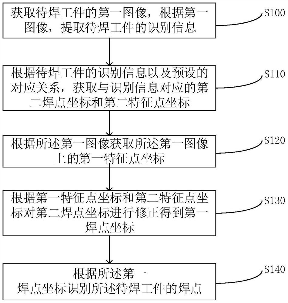
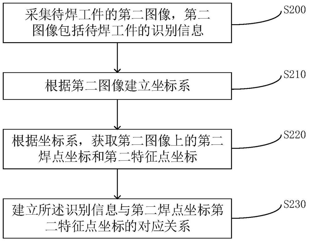
The invention relates to a welding point positioning method and a welding point positioning device. Wherein, the welding spot positioning method includes: obtaining the first image of the workpiece to be welded, and extracting the identification information of the workpiece to be welded according to the first image; according to the identification information of the workpiece to be welded and the preset corresponding relationship, obtaining the The second welding point coordinates and the second feature point coordinates; the first feature point coordinates on the first image are obtained according to the first image; the second welding point coordinates are corrected according to the first feature point coordinates and the second feature point coordinates to obtain the first feature point coordinates A welding point coordinate; identifying the welding point of the workpiece to be welded according to the first welding point coordinate. In the above welding point positioning method, by using the visual positioning mechanism to collect the first image of the workpiece to be welded in advance, the coordinates of the welding points on the first image can be obtained, which provides a basis for the subsequent welding mechanism to adjust the coordinates of the welding points. The visual positioning mechanism can be used for precise positioning, which improves the reliability of solder joint positioning.

Description

technical field [0001] The invention relates to the technical field of welding positioning, in particular to a welding point positioning method and a welding point positioning device. Background technique [0002] New energy vehicles refer to vehicles that use unconventional vehicle fuel as a power source. Usually new energy vehicles use lithium batteries to power the vehicle. With the development of the new energy vehicle industry, the capacity requirements for lithium batteries are greater. At present, a large-capacity lithium battery is composed of multiple battery modules, and each battery module includes several small cylindrical cells and a bracket for fixing the cylindrical cells. The positive pole of each cylindrical electric core is connected with the positive pole, and the negative pole is connected with the negative pole. At the same time, the negative pole of the electric core is welded to the negative bus bar through the aluminum wire and electrically connected...

Claims


Application Information

Patent Timeline
Patent Type & Authority Patents(China)
IPC IPC(8): B23K31/00B23K37/00H01M50/516H01M10/04H01M50/528
CPCB23K31/00B23K37/00H01M10/0404H01M10/0422H01M50/528Y02E60/10Y02P70/50
Inventor 吴晓东张同虎刘川杨子成
Owner CHONGQING JINKANG POWER NEW ENERGY CO LTD
Learn More