Device for compression treatment of industrial garbage
A technology for compressing treatment devices and industrial waste, which is applied to presses, manufacturing tools, etc., and can solve problems such as difficult removal of waste and inability to collect landfill leachate
- Summary
- Abstract
- Description
- Claims
- Application Information
AI Technical Summary
Problems solved by technology
Method used
Image
Examples
specific Embodiment approach 1
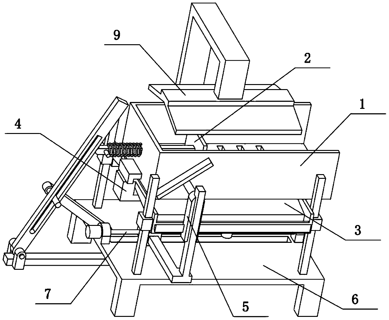
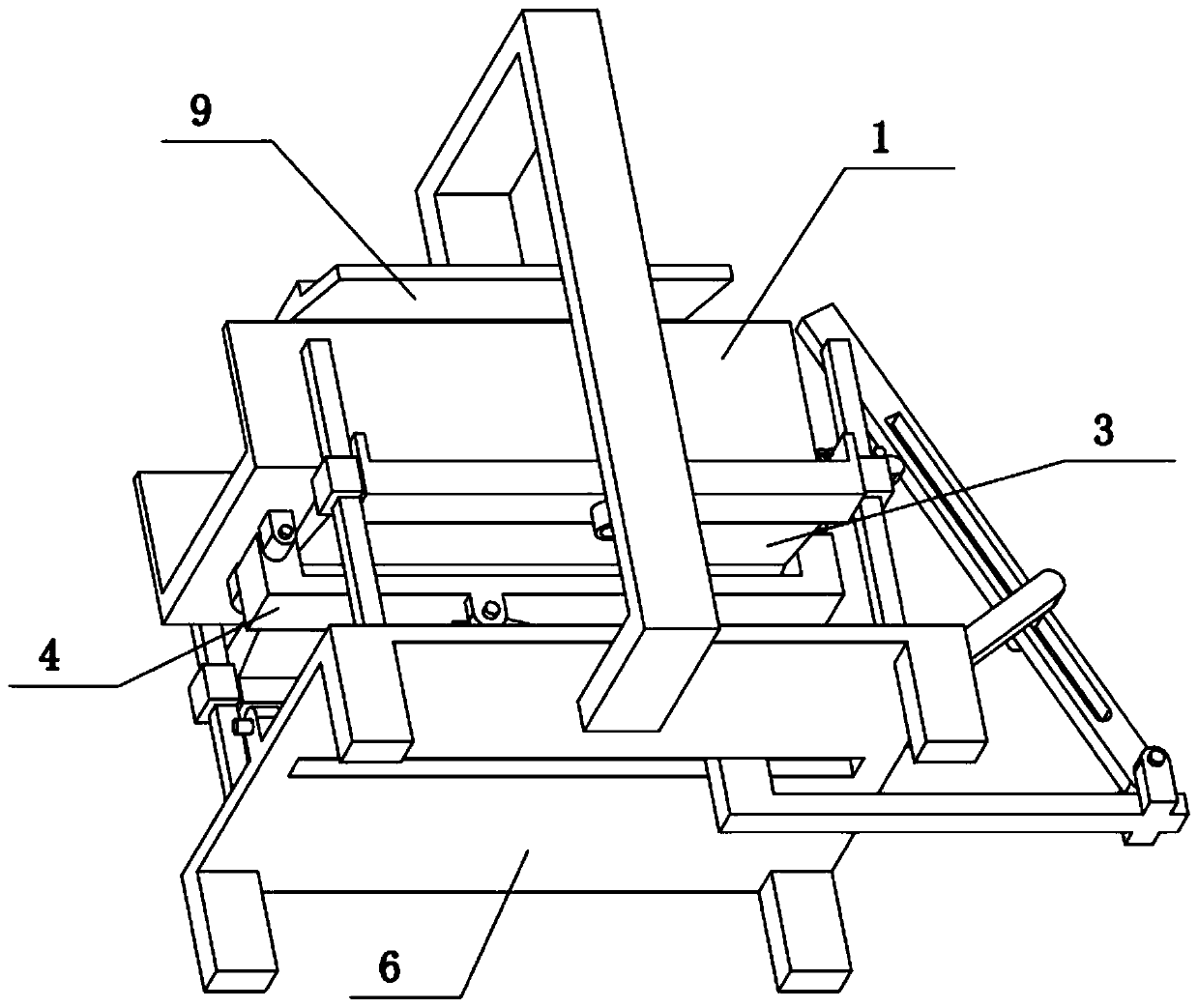
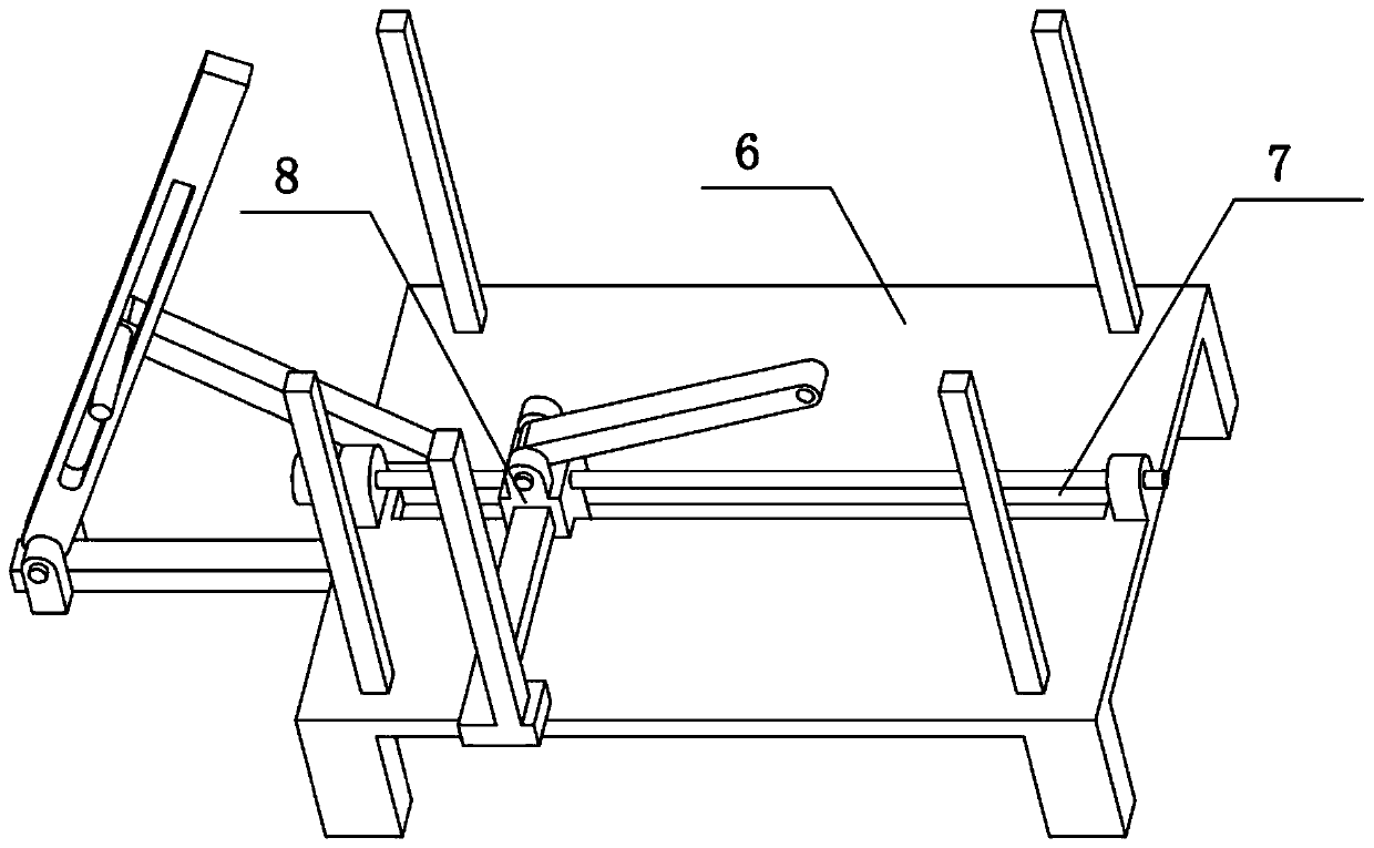
[0033] Combine below Figure 1-11 Describe this embodiment, the present invention relates to the field of garbage disposal, more specifically, an industrial garbage compression treatment device, including a compression box 1, a water permeable hole 101, a V-shaped plate 3, a liquid tank 301, left and right baffles 302, and a water outlet 304, door-shaped bracket 4 and pressing plate 9, the present invention can collect the rubbish in the rubbish after percolating hydraulic pressure.
[0034] The right side of described compression box 1 is open, and the lower side of compression box 1 is provided with a plurality of permeable holes 101, and the center of V-shaped plate 3 is high, and the front and rear ends are low, and the left and right ends of V-shaped plate 3 are all fixedly connected with left and right sides. The baffle plate 302, the front and rear ends of the V-shaped plate 3 all form liquid tanks 301, the lower sides of the two liquid tanks 301 are provided with water...
specific Embodiment approach 2
[0036] Combine below Figure 1-11To illustrate this embodiment, the industrial waste compression treatment device also includes a hinged seat I103 and a cushion block 104, the right end of the lower side of the compression box 1 is provided with a hinged seat I103, and the left end of the lower side of the compression box 1 is fixedly connected with a cushion block 104, and the door The right-hand side of door-shaped bracket 4 is hinged on the hinged seat I103, and spacer 104 rides on the left end of door-shaped bracket 4. The right end of the door-shaped bracket 4 is hinged on the hinge seat I103, so that the compression box 1 can be rotated to an inclined state, and after the compression of the garbage is completed, it is convenient for the garbage to be poured out from the compression box 1.
specific Embodiment approach 3
[0038] Combine below Figure 1-11 To illustrate this embodiment, the industrial waste compression treatment device also includes a push plate 2, a horizontal slide bar 201 and a limit pin 202. The horizontal slide bar 201 is slidably connected to the left end of the compression box 1, and the right end of the horizontal slide bar 201 is fixedly connected to a The push plate 2 and the left end of the horizontal slide bar 201 are fixedly connected with the limit pin 202, the push plate 2 is located inside the compression box 1, and the slide bar 201 between the limit pin 202 and the compression box 1 is sleeved with a compression spring. The horizontal slide bar 201 can slide left and right, and the horizontal slide bar 201 will drive the push plate 2 to slide, and the compression spring will give the limit pin 202 the power to move to the left, so that the horizontal slide bar 201 and the push plate 2 are usually in the left state. After compaction, it is not easy to come off f...
PUM
 Abstract
Description
Claims
Application Information
 - R&D
- Intellectual Property
- Life Sciences
- Materials
- Tech Scout
- Unparalleled Data Quality
- Higher Quality Content
- 60% Fewer Hallucinations
Browse by: Latest US Patents, China's latest patents, Technical Efficacy Thesaurus, Application Domain, Technology Topic, Popular Technical Reports.
© 2025 PatSnap. All rights reserved.Legal|Privacy policy|Modern Slavery Act Transparency Statement|Sitemap|About US| Contact US: help@patsnap.com


