Driving lifting chair elevator on stairs

A chair lift and stair technology, used in elevators, transportation and packaging in buildings, can solve problems such as inconvenience for the disabled, consumption of family strength, hidden dangers, etc., and achieve the effect of saving physical strength, taking up less space, and being easy to move.

Pending Publication Date: 2019-10-15
上海巨菱电梯有限公司
View PDF6 Cites 0 Cited by
  • Summary
  • Abstract
  • Description
  • Claims
  • Application Information

AI Technical Summary

Problems solved by technology

[0002] It is very inconvenient for people with disabilities to live, especially if they live in high-floor houses without elevators and want to go out for activities. They often need to rely on their family members to carry them up and down the stairs. This will not only consume the physical strength of the family members, but also cause certain security risks

Method used


Image

  • Driving lifting chair elevator on stairs
  • Driving lifting chair elevator on stairs
  • Driving lifting chair elevator on stairs

Examples


Embodiment 1

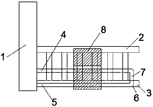
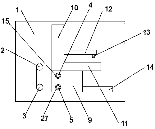
[0025] see Figure 1-4 According to an embodiment of the present invention, a stair belt-driven chair lift includes a wall 1 and an upper stair handrail 2 and a lower stair handrail 3 fixed on the wall 1. Upper handrail 2, the upper slide bar 4 and the lower bar 5 matched with the handrail 3 under the stairs, the upper slide bar 4 and the lower bar 5 are movable with a drive lift chair body 8, and the drive lift chair body 8 includes a control seat 9, a chair back 10, a seat 11, a foot pad 14, a handrail 12 and a control switch 13 arranged on the handrail 12, and the end of the handrail 3 under the stairs is far away from the wall 1 and is fixed with a slide bar Fixed block 6, described slide bar fixed block 6 is provided with fixed support bar 7, and described fixed support bar 7 is all fixedly connected with described upper slide bar 4, described lower bar 5 respectively, and described driving lift chair body 8 There is a drive device for moving up and down.

Embodiment 2

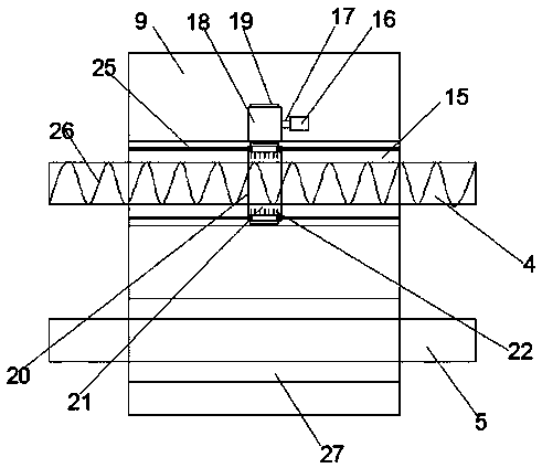
[0027] see Figure 1-4 , in a specific application, for the up and down moving driving device, the up and down moving driving device includes a positive and negative motor 16 fixedly arranged in the control seat 9, and the positive and negative motor 16 is provided with a motor shaft 17, so The motor shaft 17 is fixedly provided with a driving wheel 18, and the driving wheel 18 is provided with main gear teeth 19.

[0028] In a specific application, for the control seat 9, the first chute 15 and the second chute 27 are respectively provided in the control seat 9, and the upper sliding rod 4 and the lower sliding rod 5 pass through the first chute respectively. A chute 15 and the second chute 27 .

[0029] In a specific application, for the first chute 15, a driven wheel 20 is movable in the first chute 15, and a driven wheel 20 is provided with a driven gear 23, and the driven gear 23 is connected to the driven gear 23. The above-mentioned main gear teeth 19 are flexibly con...


PUM


Abstract

The invention discloses a driving lifting chair elevator on stairs. The elevator comprises a wall, an upper stair handrail and a lower stair handrail, wherein the upper stair handrail and the lower stair handrail are fixed on the wall; an upper sliding rod and a lower sliding rod are fixedly arranged on the wall; the upper sliding rod and the lower sliding rod are respectively matched with the upper stair handrail and the lower stair handrail; a driving lifting chair body is movably arranged on the upper sliding rod and the lower sliding rod; the driving lifting chair body comprises a controlseat, a chair back, a chair seat, foot pads, armrests and a control switch arranged on the armrests; a sliding rod fixing block is fixedly arranged on one end, away from the wall, of the lower stair handrail; and a fixing supporting rod is arranged on the sliding rod fixing block. The elevator has the beneficial effects that by using the control switch through one key, the disabled can sit on thedriving lifting chair body to freely go upstairs and downstairs, the life of the disabled is greatly facilitated, the physical strength of a family caring for the disabled is saved, the chair can be folded and unfolded, and the space is saved when the chair is not used.

Description

technical field [0001] The invention relates to the field of a stair belt driven chair lift, in particular to a stair belt driven chair lift. Background technique [0002] It is very inconvenient for people with disabilities to live, especially if they live in a high-floor house without an elevator and want to go out for activities. They often need to rely on their family members to carry them up and down the stairs. This will not only consume the physical strength of the family members, but also Certain security risks. [0003] In order to solve this problem, a kind of stair belt drive chair lift is therefore needed to solve this problem. Contents of the invention [0004] The object of the present invention is to provide a stair belt driven chair lift to solve the problems raised in the above-mentioned background technology. [0005] Technical scheme of the present invention is realized like this: [0006] A stair belt-driven chairlift, comprising a wall and an uppe...

Claims


Application Information

Patent Timeline
Patent Type & Authority Applications(China)
IPC IPC(8): B66B9/08B66B11/02B66B11/04
CPCB66B9/08B66B9/0807B66B9/0853
Inventor 鲍文杰
Owner 上海巨菱电梯有限公司
Why Eureka
Try Eureka