Turbocharger exhaust gas valve base device

A technology of turbocharger and waste gas valve, which is applied to gas turbine devices, machines/engines, engine components, etc., can solve the problems of poor anti-attenuation ability, unfavorable sealing performance, deteriorated sealing performance, etc., and achieves less wear and better sealing. Performance and durability, low machining concentricity requirements

Pending Publication Date: 2019-10-15
WUXI CUMMINS TURBO TECH
View PDF0 Cites 0 Cited by
  • Summary
  • Abstract
  • Description
  • Claims
  • Application Information

AI Technical Summary

Problems solved by technology

During use, due to internal combustion engines, especially diesel internal combustion engines, the exhaust gas is mixed with metal particles and solid salt particles, which are easy to stick to the valve seat plane of the volute 1 and not easy to completely shake off under high temperature conditions, thereby deteriorating its sealing performance. During the switch collision process of the wastegate valve, the wear material is easy to protrude from the plane at the impact position of the valve plate, which is not conducive to its sealing performance, and its anti-attenuation ability is poor

Method used


Image

  • Turbocharger exhaust gas valve base device
  • Turbocharger exhaust gas valve base device
  • Turbocharger exhaust gas valve base device

Examples


Embodiment 1

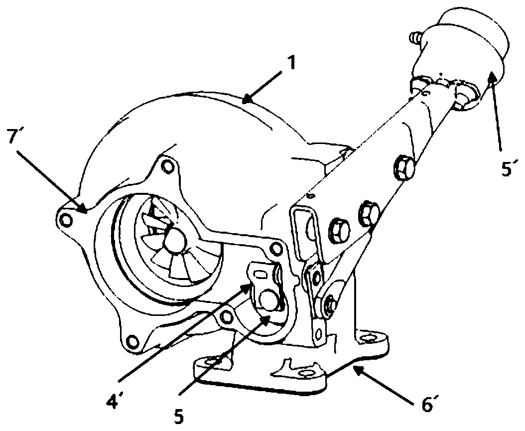
[0025] Such as Figure 4 As shown, a turbocharger exhaust valve seat device related to the present invention includes a volute 1, a bypass valve assembly 2, and the bypass valve assembly 2 includes a valve pin 3, a fin 4 and a valve plate 5, and the fin The sheet 4 is arranged between the valve pin 3 and the valve sheet 5, the valve sheet 5 is movably arranged on the valve pin 3, and the valve sheet 5 can slightly swing up and down on the valve pin 3;

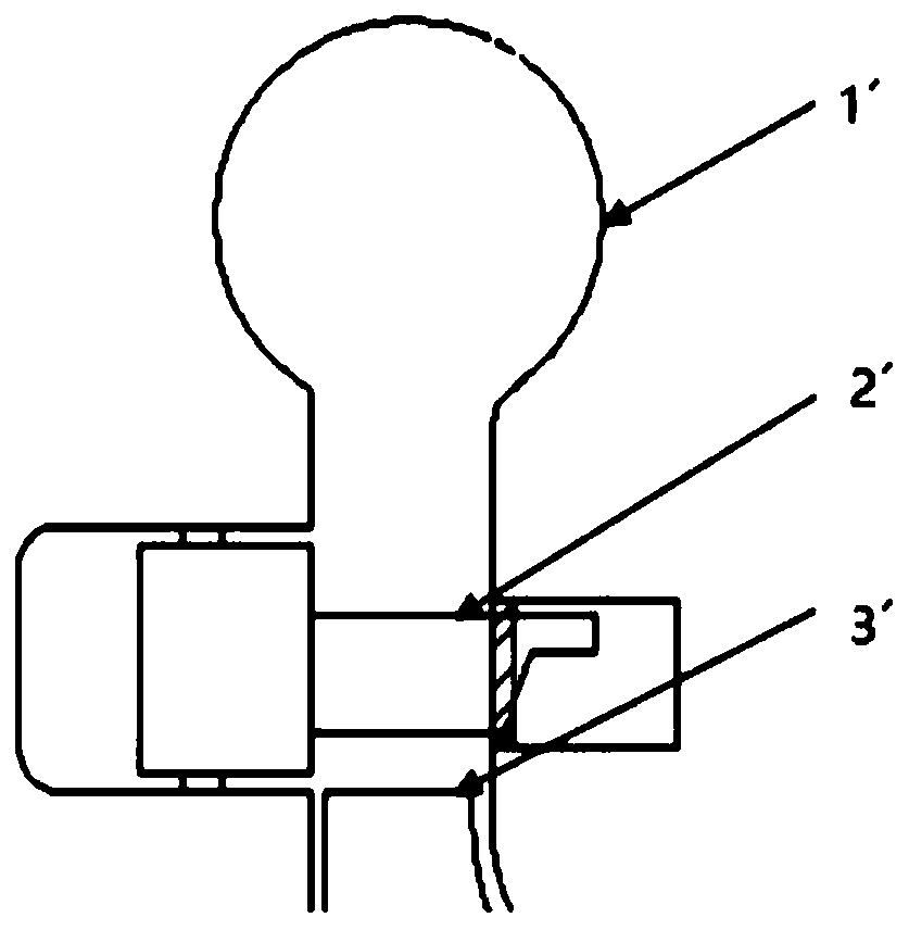
[0026] In order to improve the wastegate sealing ability, such as Figure 4 and Figure 5 As shown, a tapered surface 9 is processed on the valve seat of the volute 1, and coincides with the center of the bypass hole 6, and its intersection line is a circular line on the same plane, so as to realize the connection with the valve plate 5 of the wastegate valve. Line contact is performed to perform line sealing to improve the sealing performance of the wastegate valve. However, the concentricity between the tapered surface 9 of...

Embodiment 2

[0030] Such as Figure 7 As shown, the valve seat 7 in embodiment 2 is the same as that in embodiment 1, and a circle of sealing annular surface 8 is set on the edge of bypass hole 6, the difference is that a ring lower than the sealing annular surface 8 is provided outside the sealing annular surface 8. The plane 10, and the height difference is controlled within 1mm. Similar to the design of the step, the plane below the sealing annular surface 8 can also be used to make the valve plate 5 bounce back to the equilibrium position and fit the sealing annular surface 8 on the valve seat 7 to achieve the same technical effect.


PUM


Abstract

The invention relates to a turbocharger exhaust gas valve base device. The turbocharger exhaust gas valve base device comprises a volute and a bypass valve assembly; the bypass valve assembly comprises a valve pin, fins and a valve plate, the valve plate is movably arranged on the valve pin, the volute is provided with a bypass hole matched with the bypass valve assembly and a valve base, the valve base is provided with a conical face, the center of the conical face and the center of the bypass hole coincide, a seal annular face is arranged on the edge of the bypass hole in the conical face, and the outer diameter of the seal annular face is smaller than the outer diameter of the valve plate. The device is simple and reasonable in structure, through design of the bypass hole and the valvebase, the seal durability capacity of the bypass valve in the use can be effectively improved.

Description

technical field [0001] The invention relates to a waste gas valve seat device of a turbocharger, belonging to the technical field of turbocharger equipment. Background technique [0002] A turbocharger is a device that provides compressed gas with a pressure greater than the ambient pressure for the cylinder of an internal combustion engine. The typical structure is as follows figure 1 shown. Generally speaking, a turbocharger is composed of a turbine, a compressor, etc. The turbine of the core component is driven by the exhaust gas of the flow channel of the volute assembly, so that the impeller of the core component rotates to compress the gas, and under the pressure of the pressure shell assembly , to increase the air pressure in the cylinder of the internal combustion engine and increase its density, thereby helping the engine improve power output and emission control. [0003] In the process of internal combustion engine development, its low-speed and high-speed power...

Claims


Application Information

Patent Timeline
Patent Type & Authority Applications(China)
IPC IPC(8): F02B37/18F01D25/24F02C6/12
CPCF01D25/24F02B37/183F02C6/12Y02T10/12
Inventor 邹健吉姆.迈凯文
Owner WUXI CUMMINS TURBO TECH
Why Eureka
Try Eureka