
Water flow sensor and fuel gas water heater

A technology of water flow sensor and temperature sensor, which is applied in the direction of fluid heater, liquid/fluid solid measurement, application of electromagnetic flowmeter to detect fluid flow, etc. It can solve problems such as waterway damage, waterway parts freezing and cracking, water flow sensor damage, etc. , to achieve the effect of buffering water pressure and preventing the shell from freezing and cracking

Pending Publication Date: 2019-10-15
GUANGDONG MACRO GAS APPLIANCE
View PDF0 Cites 8 Cited by
  • Summary
  • Abstract
  • Description
  • Claims
  • Application Information

AI Technical Summary

Problems solved by technology

[0002] In winter, due to the rapid drop in temperature, when the water in the waterway of the gas water heater freezes, the ice will expand outwards, causing damage to the components of the waterway, and in severe cases, it will cause the components of the waterway to freeze and crack; most of the current market Most gas water heaters do not have antifreeze cracking structures, and are usually protected by artificial drainage, while gas water heaters with antifreeze cracking usually use antifreeze heating elements on the water pipes or are controlled by programs under the action of water pumps. circulate the water inside
These solutions still have many loopholes and deficiencies in actual operation. For example, the parts of the water heater tank or the waterway are frozen and cracked due to the user’s power failure, forgetting to drain water, etc., and because there are many precision parts in the water flow sensor. Flow sensors are especially vulnerable to damage from water freezing in the waterway

Method used


Image

  • Water flow sensor and fuel gas water heater
  • Water flow sensor and fuel gas water heater
  • Water flow sensor and fuel gas water heater

Examples


Embodiment Construction

[0021] The conception, specific structure and technical effects of the present invention will be clearly and completely described below in conjunction with the embodiments and accompanying drawings, so as to fully understand the purpose, characteristics and effects of the present invention. Obviously, the described embodiments are only some of the embodiments of the present invention, rather than all embodiments. Based on the embodiments of the present invention, those skilled in the art can obtain other embodiments without paying creative work. All belong to the scope of protection of the present invention. In addition, all connection relationships mentioned in this article do not refer to the direct connection of components, but mean that a better connection structure can be formed by adding or reducing connection accessories according to specific implementation conditions. The various technical features in the invention can be combined interactively on the premise of not co...


PUM


Abstract

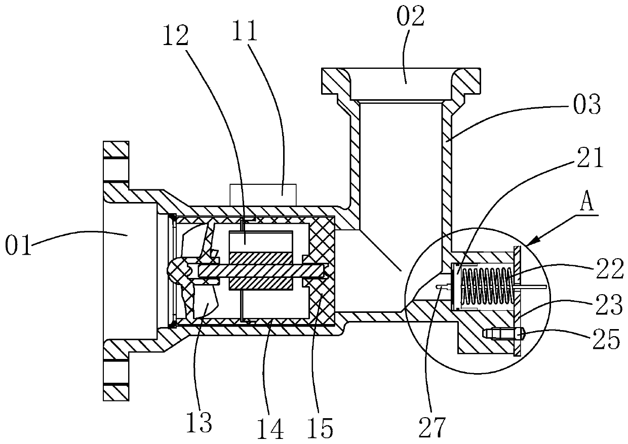
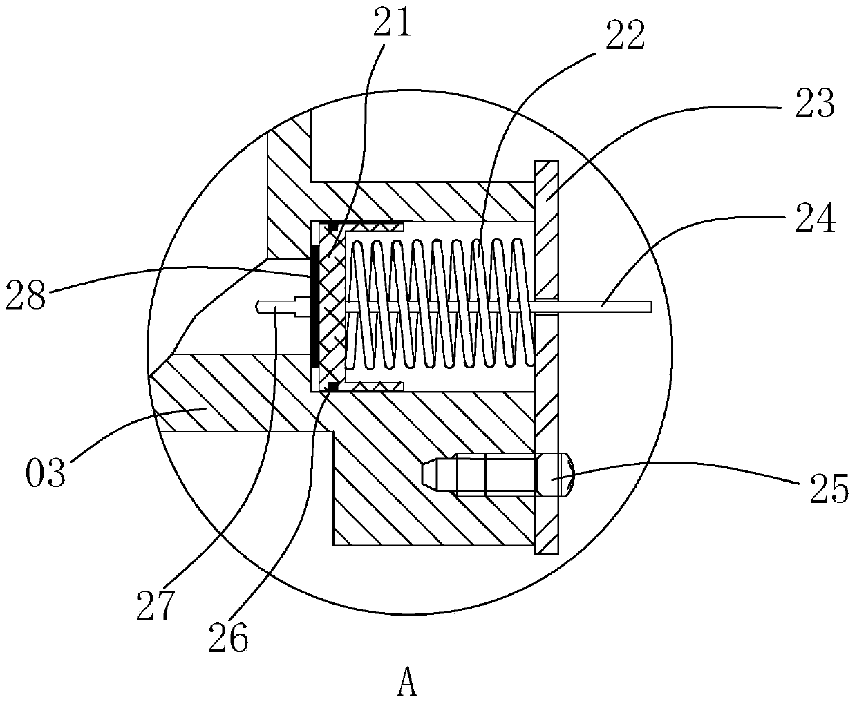
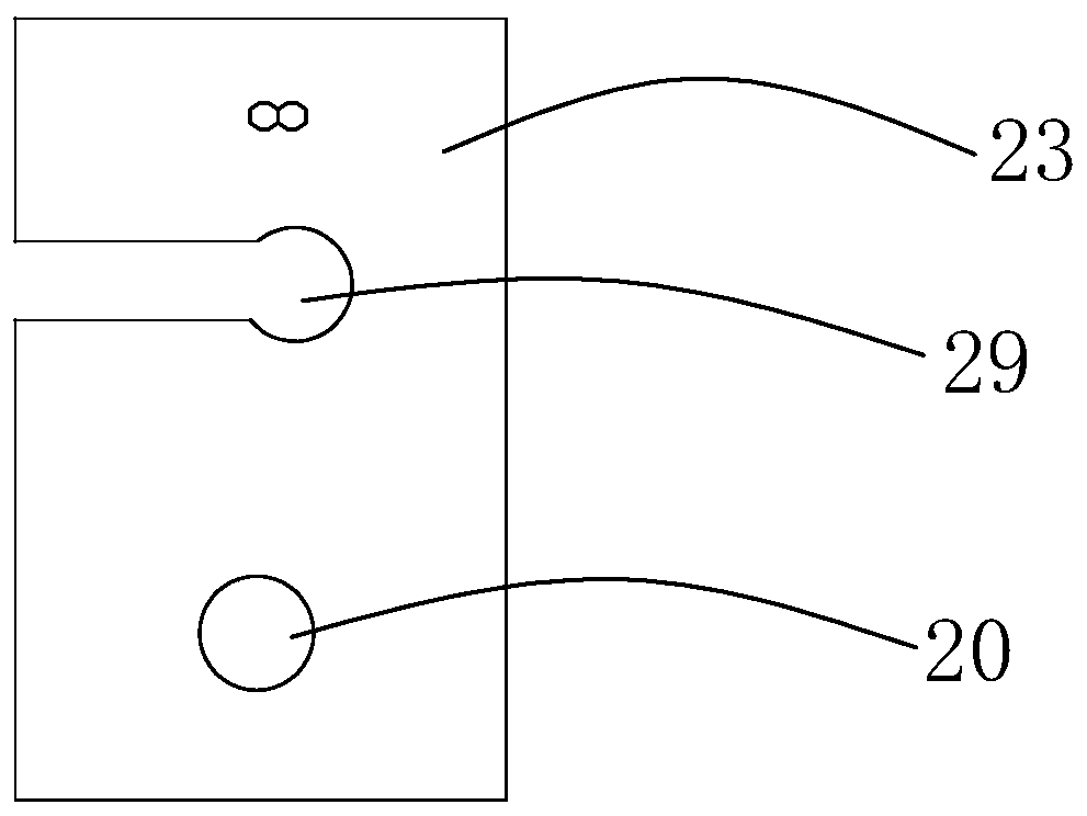
The invention discloses a water flow sensor and a fuel gas water heater. The water flow sensor comprises a shell. The shell is provided with a Hall flowmeter component. A pressure relief channel is arranged on the shell, the pressure relief channel has a left section and a right section, a piston is arranged in the pressure relief channel, the piston is arranged between the left section and the right section, the left section is connected with an inner cavity of the shell, an elastic component is arranged in the right section. A right side of the right section is provided with an end cover, the end cover is detachably connected to the shell, and the end cover is provided with a venting port. When water in a waterway of the fuel gas water heater freezes and expands outwardly, because a freezing process is a slow process, an ice cube is squeezed towards the piston, the squeezed piston moves to the right, air in the right section is vented to the outside air through the venting port, an enough space is released for the expanded ice cube so as to prevent the shell from being frosted and cracked or the Hall flowmeter component from being damaged, and a protection effect can be achievedunder a condition that the water heater is power off.

Description

technical field [0001] The invention relates to the technical field of gas water heaters, in particular to a water flow sensor and a gas water heater. Background technique [0002] In winter, due to the rapid drop in temperature, when the water in the waterway of the gas water heater freezes, the ice cubes will expand outwards, causing damage to the components of the waterway, and in severe cases, it will cause the components of the waterway to freeze and crack; most of the current market Most of the gas water heaters do not have anti-freeze crack structure, usually through artificial drainage to play a protective role, while gas water heaters with anti-freeze crack usually use an anti-freeze heating body on the water pipe or control it under the action of the water pump through the program. Circulate the water flow inside. These solutions still have many loopholes and deficiencies in actual operation. For example, the parts of the water heater tank or the waterway are froz...

Claims


Application Information

Patent Timeline
Patent Type & Authority Applications(China)
IPC IPC(8): G01F1/58G01F15/10G01F15/14F24H9/20
CPCG01F1/58G01F15/10G01F15/14F24H9/2035
Inventor 艾穗江刘兵阳悠悠李井龙
Owner GUANGDONG MACRO GAS APPLIANCE
Learn More