
Eureka
For R&D, Eureka makes reading and utilizing patents & technical documents easy.
Eureka AIR
Designed for self-driven R&D workflows. Generate viable solutions, solve complex R&D challenges, empower your innovation with AI.

Eureka Materials
Designed for material experts only. Revolutionize your material R&D, from search, analyze, to developing new materials.

TechResearch
Generate reliable direction feasibility study reports for your R&D in just a few steps.

TechSeek
Discover and master advanced knowledge NOW. Basics, ideas, possibilities, all at once.

TechMind
As an expert in R&D Theories, TechMind can generates customized viable solutions instantly.

TechRisk
Analyze your overall solution with one click, know your potential R&D risks in advance.

TechMonitor
Get weekly tech updates, stay abreast of the latest tech innovations and key insights.
Camera Optical Lens
A technology of optical lens and optical total length, which is applied in the field of optical lens, can solve the problems of irrational setting of focal power, lens distance and lens shape, inability to meet large aperture, ultra-thin, wide-angle, etc., and achieve good optical performance Effect
- Summary
- Abstract
- Description
- Claims
- Application Information
AI Technical Summary
Problems solved by technology
Method used
Image

Examples
no. 1 approach
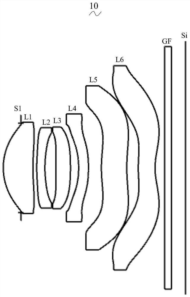
[0051] Please refer to the accompanying drawings, the present invention provides a camera optical lens 10 . figure 1 Shown is the imaging optical lens 10 of the first embodiment of the present invention, and the imaging optical lens 10 includes six lenses. Specifically, the imaging optical lens 10 includes, from the object side to the image side in sequence: an aperture S1, a first lens L1 with a positive refractive power, a second lens L2 with a negative refractive power, and a third lens L2 with a positive refractive power. A lens L3, a fourth lens L4 having a negative refractive power, a fifth lens L5 having a positive refractive power, and a sixth lens L6 having a negative refractive power. An optical element such as an optical filter (filter) GF may be disposed between the sixth lens L6 and the image plane Si.
[0052]In this embodiment, the focal length of the entire imaging optical lens is defined as f, the focal length of the fifth lens L5 is f5, and the following rel...
no. 2 approach
[0150] The second embodiment is basically the same as the first embodiment, and the meanings of symbols are the same as those of the first embodiment. For the structure of the imaging optical lens 20 of the second embodiment, please refer to Figure 5 As shown, only the differences are listed below.
[0151] Table 5 and Table 6 show design data of the imaging optical lens 20 according to the second embodiment of the present invention.
[0152] 【table 5】
[0153]
[0154]
[0155] Table 6 shows the aspheric surface data of each lens in the imaging optical lens 20 according to the second embodiment of the present invention.
[0156] 【Table 6】
[0157]
[0158] Table 7 and Table 8 show the design data of inflection point and stagnation point of each lens in the imaging optical lens 20 according to the second embodiment of the present invention.
[0159] 【Table 7】
[0160] Number of inflection points Inflection point position 1 Inflection point positio...
no. 3 approach
[0167] The third embodiment is basically the same as the first embodiment, and the meanings of symbols are the same as those of the first embodiment. For the structural form of the imaging optical lens 30 of the third embodiment, please refer to Figure 9 As shown, only the differences are listed below.
[0168] Table 9 and Table 10 show design data of the imaging optical lens 30 according to the third embodiment of the present invention.
[0169] 【Table 9】
[0170]
[0171]
[0172] Table 10 shows the aspheric surface data of each lens in the imaging optical lens 30 of the third embodiment of the present invention.
[0173] 【Table 10】
[0174]
[0175] Table 11 and Table 12 show the design data of the inflection point and the stagnation point of each lens in the imaging optical lens 30 according to the third embodiment of the present invention.
[0176] 【Table 11】
[0177]
[0178]
[0179] 【Table 12】
[0180] Stationary number Stationary pos...
PUM
| Property | Measurement | Unit |
|---|---|---|
| Entrance pupil diameter | aaaaa | aaaaa |
| Entrance pupil diameter | aaaaa | aaaaa |
| Entrance pupil diameter | aaaaa | aaaaa |
Abstract
Description
Claims
Application Information
 - R&D Engineer
- R&D Manager
- IP Professional
- Industry Leading Data Capabilities
- Powerful AI technology
- Patent DNA Extraction
Browse by: Latest US Patents, China's latest patents, Technical Efficacy Thesaurus, Application Domain, Technology Topic, Popular Technical Reports.
© 2024 PatSnap. All rights reserved.Legal|Privacy policy|Modern Slavery Act Transparency Statement|Sitemap|About US| Contact US: help@patsnap.com