
Parallel operation method for transformers based on current relay

A technology of current relay and operating method, which is applied in the direction of conversion equipment that can be converted to DC without intermediate conversion, AC power input is converted into AC power output, electrical components, etc., and can solve current phase difference, low transformer operating efficiency, power consumption, etc. Problems such as poor power supply reliability in system operation, to achieve the effect of improving power supply reliability, reducing backup capacity, and improving operating efficiency

Inactive Publication Date: 2019-10-15
SANCHU OF CHINA RAILWAY TUNNEL GROUP
View PDF4 Cites 9 Cited by
  • Summary
  • Abstract
  • Description
  • Claims
  • Application Information

AI Technical Summary

Problems solved by technology

[0003] The transformers in the prior art solution are connected in parallel. When there is no load, there is a circulating current between the secondary sides of the parallel transformers; when the load is on, the parallel transformers cannot reasonably share the load according to their capacity, and the currents on the secondary sides of the parallel transformers have phase differences. , leading to poor reliability of power supply in power system operation, redundant reserve capacity, and low efficiency of transformer operation

Method used


Image

  • Parallel operation method for transformers based on current relay

Examples


Embodiment Construction

[0026] The implementation mode of the present invention is illustrated by specific specific examples below, and those who are familiar with this technology can easily understand other advantages and effects of the present invention from the contents disclosed in this description. Obviously, the described embodiments are a part of the present invention. , but not all examples. Based on the embodiments of the present invention, all other embodiments obtained by persons of ordinary skill in the art without making creative efforts belong to the protection scope of the present invention.

[0027] Those skilled in the art know that the per unit value is a kind of relative unit system, and it is a numerical notation method commonly used in power system analysis and engineering calculations. dimensionless). In power system calculations, per unit values ​​are also widely used. The per unit value is relative to a certain benchmark value. For the same famous value, when the benchmark v...


PUM


Abstract

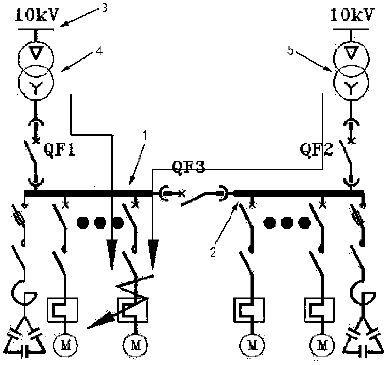
The embodiment of the invention discloses a parallel operation method for transformers based on a current relay. Circuit breakers are connected between several sections of buses. A transformer is connected between a high-voltage power bus and each section of bus. The transformers have equal rated voltage, approximately same transformation ratio, same connection group mark number, approximately equal short-circuit impedance per-unit value and approximately same short-circuit impedance angle. The error of the transformation ratios of the transformers does not exceed + / -0.5%. The errors of the short-circuit impedance per-unit values and of the short-circuit impedance angles of the transformers do not exceed + / -10%. When the current of a first transformer exceeds 5% of the set value, a circuitbreaker QF2 is changed from a normally open state to a normally closed state, and a second transformer is energized and put into operation. When the current of the first transformer drops to the setvalue, the circuit breaker QF2 is reset, and the second transformer is out of operation. The method of the invention ensures that there is no loop current in the windings during no-load operation of the transformers, ensures that the load distribution is directly proportional to the capacity, improves the reliability of power supply, reduces the reserve capacity, and improves the operation efficiency.

Description

technical field [0001] The embodiment of the present invention relates to the technical field of power supply, and in particular to a method for parallel operation of transformers based on a current relay. Background technique [0002] At present, the parallel operation of transformers means that the primary windings of two or more transformers are connected in parallel on the busbar of the same voltage, and the secondary windings are connected in parallel on the busbar of another voltage. When a transformer fails, other transformers running in parallel can still continue to run to ensure the power consumption of important users; or when the transformer needs to be repaired, the spare transformer can be connected in parallel first, and then the transformer to be repaired is cut off for repair, which can ensure The planned maintenance of the transformer can ensure uninterrupted power supply and improve the reliability of power supply. In addition, due to the strong seasonali...

Claims


Application Information

Patent Timeline
Patent Type & Authority Applications(China)
IPC IPC(8): H02J3/00H02P13/00
CPCH02J3/005H02P13/00
Inventor 彭兴强李友坤董子龙张雷赏自飞李建高黄海山黎鸣沙平平王龙兵许涛陈瑜吴永恒严雪军吴江林
Owner SANCHU OF CHINA RAILWAY TUNNEL GROUP
Learn More