LLC Sensorless Synchronous Rectification Control Method Based on Phase Shift Angle Feedforward

A technology of synchronous rectification and control method, which is applied in the direction of control/adjustment system, instrument, output power conversion device, etc. It can solve the problems of not considering the change of the maximum gain value, low decoupling accuracy, and increased system hardware cost, etc., to achieve Solve the hysteresis of synchronous rectification control, ensure safe operation, and reduce hardware costs

Active Publication Date: 2019-10-11
HEFEI UNIV OF TECH
View PDF5 Cites 0 Cited by
  • Summary
  • Abstract
  • Description
  • Claims
  • Application Information

AI Technical Summary

Problems solved by technology

[0007] 1) The method of requiring additional sensors increases the hardware cost of the system
[0008] 2) The decoupling accuracy of the sensorless method is not high, and the change of the maximum gain value when the load changes is not considered. In the decoupling process, the hysteresis of the output voltage response is not considered, which leads to the hysteresis of the synchronous rectification control. When the input voltage suddenly increases Or in the case of a sudden load drop, a large circulating current will be generated on the secondary side of the transformer, which is not conducive to the safe operation of the system

Method used


Image

  • LLC Sensorless Synchronous Rectification Control Method Based on Phase Shift Angle Feedforward
  • LLC Sensorless Synchronous Rectification Control Method Based on Phase Shift Angle Feedforward
  • LLC Sensorless Synchronous Rectification Control Method Based on Phase Shift Angle Feedforward

Examples


Embodiment Construction

[0055] The technical solutions of the present invention will be clearly and completely described below in conjunction with the accompanying drawings.

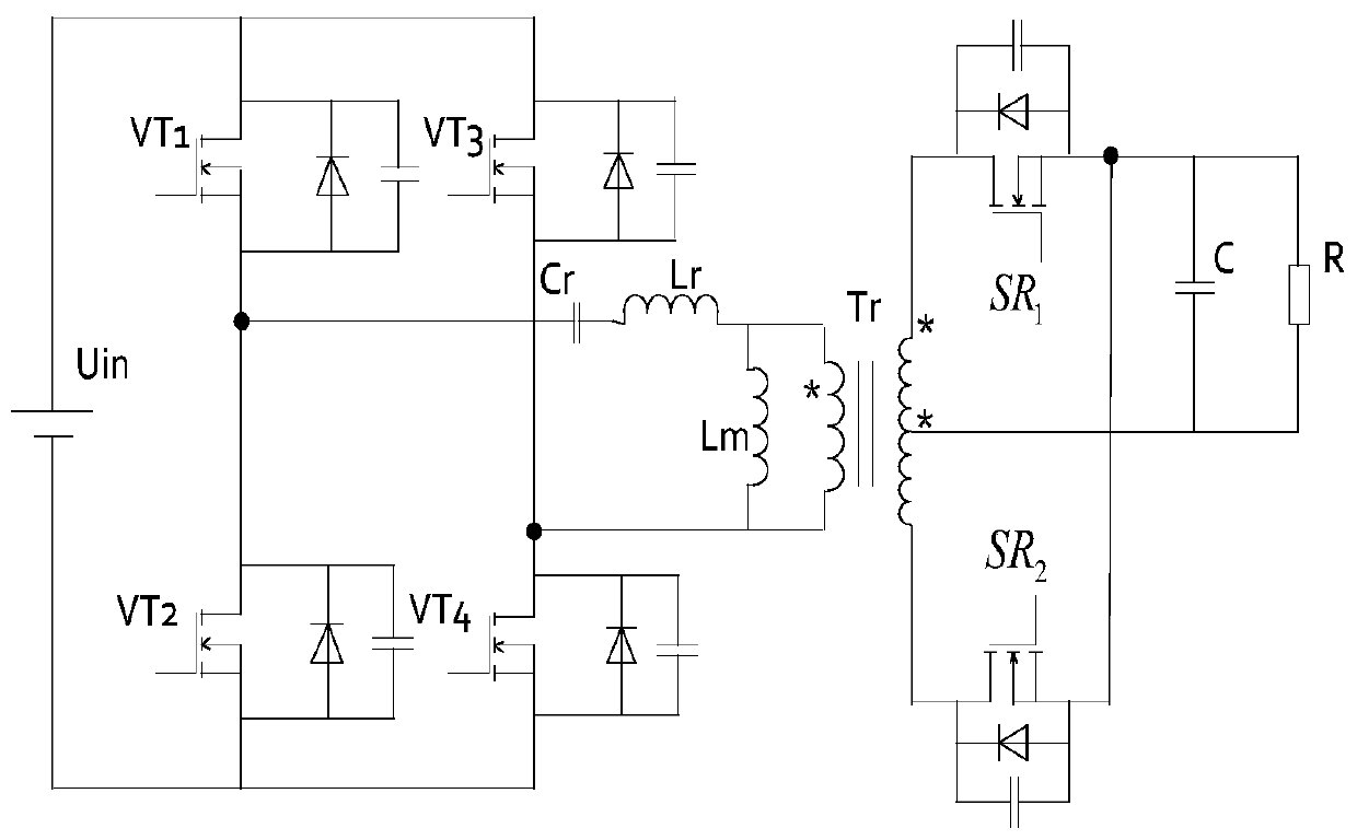
[0056] figure 1 It is a circuit scheme of the present invention. u in for the input power supply, VT 1 -VT 4 is the primary switch tube of the transformer, C r is the resonant capacitor, L r is the resonant inductance, L m is the magnetizing inductance, T r For high frequency transformers, SR 1 and SR 2 It is a synchronous rectifier tube, C is a filter capacitor, and R is a load. When the frequency conversion control in the hybrid control is adopted, the switching tube VT 1 with VT 4 Simultaneously on and off, the switch tube VT 2 with VT 3 Simultaneously on and off, the switching tubes of the same bridge arm are complementary conducting, and the duty cycle of each switching tube is fixed at 50% after ignoring the dead time, by changing the switching frequency f s to adjust the output voltage. The corresponding w...


PUM


Abstract

The invention discloses a LLC sensorless synchronous rectification control method based on phase shift angle feedforward. Using the relationship between the switching frequency and the phase shift angle under synchronous rectification drive and hybrid control when the same set voltage is reached, the precise synchronous rectification is realized through an optimization algorithm, and the phase shift angle feedforward control is introduced to solve the output voltage response The hysteresis of the optimization algorithm leads to the problem of control lag. The control method disclosed in the present invention realizes synchronous rectification without increasing the cost of system hardware, further improves the efficiency of the LLC resonant converter, solves the hysteresis of the optimization algorithm control through the phase shift angle feedforward control, and avoids power supply and load When there is a sudden change, a circulating current is generated on the secondary side of the transformer, which affects the safe operation of the system.

Description

technical field [0001] The invention relates to a synchronous rectification control method applied to an LLC resonant converter. Background technique [0002] When the LLC resonant converter is applied to low-voltage and high-current output occasions, the rectification loss on the secondary side of the transformer will become non-negligible. In order to further improve system efficiency, an effective LLC synchronous rectification scheme is needed. However, the driving situation of the synchronous rectification tube of the LLC resonant converter is relatively complicated, and it is difficult to directly obtain an accurate synchronous rectification driving signal. In order to achieve precise synchronous rectification, people have made various efforts, the literature "Wang J, Lu B. Open loop synchronous rectifier driver for LLC resonant converter [J]. 2013:2048-2051." (Wang J, Lu B. with In the open-loop synchronous rectifier drive of LLC resonant converter [J]. 2013, 2048-205...

Claims


Application Information

Patent Timeline
Patent Type & Authority Patents(China)
IPC IPC(8): H02M3/335H02M7/219
CPCH02M3/33592H02M7/219H02M1/0025Y02B70/10
Inventor 张兴颜瑄赵文广刘闯王付胜
Owner HEFEI UNIV OF TECH
Why Eureka
Try Eureka