Power control circuit of battery management system

A technology of battery management system and power control circuit, which is applied in the direction of battery disconnection circuit, battery circuit device, circuit device, etc., which can solve the problems of over-discharge damage of battery cells and inability to terminate battery cells, so as to avoid over-discharge damage and ensure Normal operation and improved safety effect

Pending Publication Date: 2019-10-15
SUNWODA ELECTRONICS
View PDF6 Cites 4 Cited by
  • Summary
  • Abstract
  • Description
  • Claims
  • Application Information

AI Technical Summary

Problems solved by technology

[0005] The main purpose of the present invention is to provide a power supply control circuit for a battery management system, which aims to solve the problems in the prior art that when the main control chip of the battery management system crashes or is damaged, the battery cannot be terminated to continue to supply power, and the battery Technical issues that create a risk of overdischarge damage

Method used


Image

  • Power control circuit of battery management system
  • Power control circuit of battery management system

Examples


Embodiment Construction

[0021] It should be understood that the specific embodiments described here are only used to explain the present invention, not to limit the present invention.

[0022] The technical solutions in the embodiments of the present invention will be clearly and completely described below in conjunction with the accompanying drawings in the embodiments of the present invention. Obviously, the described embodiments are only part of the embodiments of the present invention, not all of them. . Based on the embodiments of the present invention, all other embodiments obtained by persons of ordinary skill in the art without creative efforts fall within the protection scope of the present invention.

[0023] Those skilled in the art will understand that unless otherwise stated, the singular forms "a", "an", "the", "above" and "the" used herein may also include plural forms. It should be further understood that the word "comprising" used in the description of the present invention refers t...


PUM


Abstract

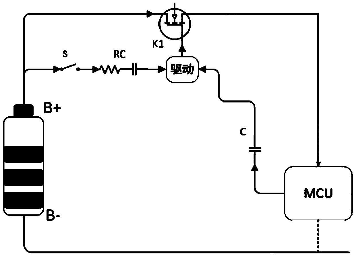
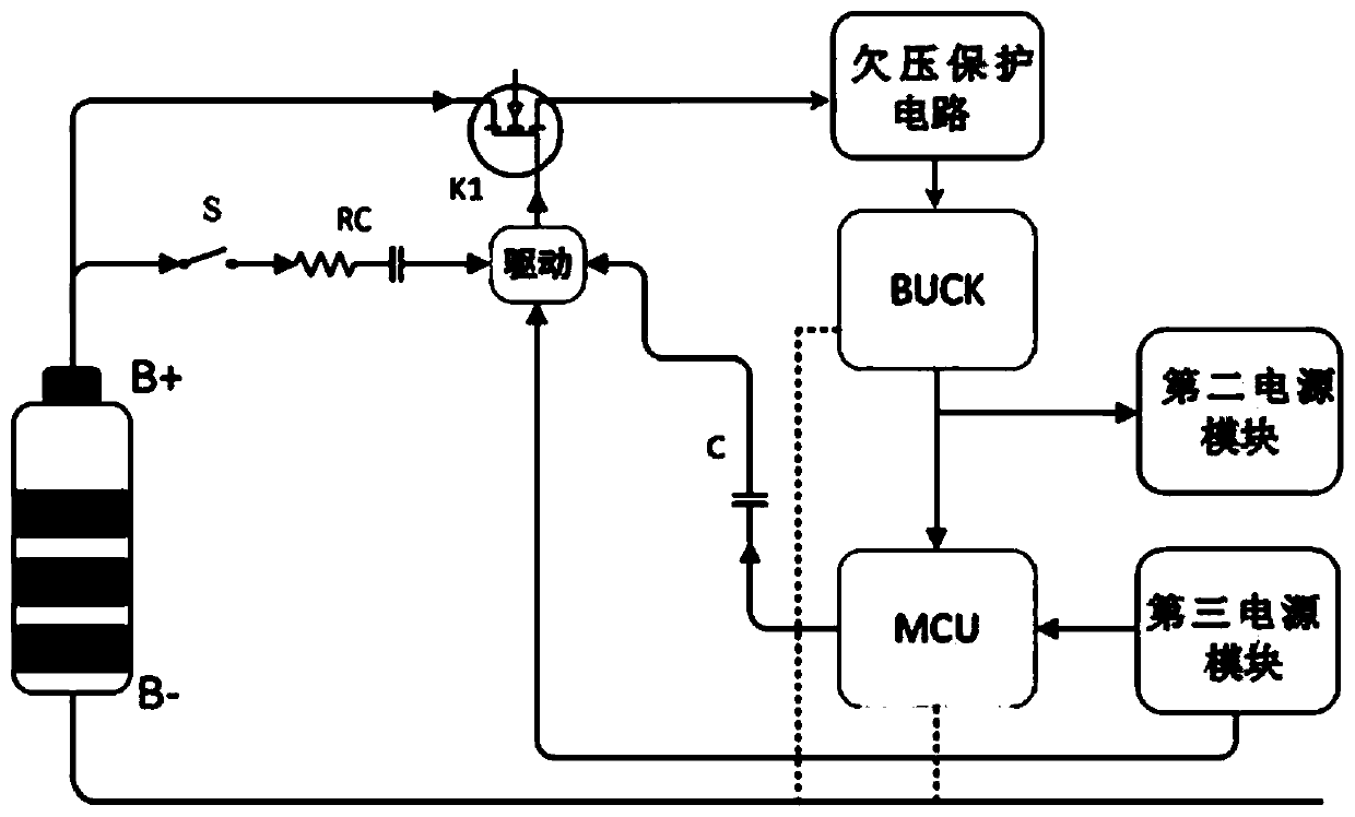
The invention discloses a power control circuit of a battery management system. The circuit includes a button switch S, an RC delay circuit, a normally open switch tube K1, a driving circuit, an MCU and a capacitor. The MCU is connected with the positive pole of a first power module through the normally open switch tube K1. The driving circuit is connected with the MCU through the capacitor. Whenthe MCU works normally, the MCU outputs a PWM signal to the capacitor to drive the normally open switch tube K1 to be closed through the driving circuit. When the MCU fails, the MCU outputs a high-level signal or a low-level signal to the capacitor to turn off the normally open switch tube K1. When the MCU fails, the normally open switch tube K1 can be automatically turned off. Thus, the self-protection function of the circuit is achieved, the risk of over-discharge damage of the cells is avoided, and the safety of the electronic components in the circuit is improved. When automatic disconnection occurs, the detection personnel can discover and maintain the fault in time to ensure normal operation of the system.

Description

technical field [0001] The invention relates to the technical field of batteries, in particular to a power supply control circuit of a battery management system. Background technique [0002] For home energy storage, communication base stations, data centers and other fields, the scale of lithium battery systems for backup power is gradually increasing. A reasonable power control circuit of the battery management system can effectively improve the stability of the system and help simplify the system control logic. Improving the safety and reliability of the system plays a positive role in promoting the maturity of the system and the promotion of the market. [0003] A micro control unit (MCU), also known as a single-chip microcomputer or a single-chip microcomputer, is to appropriately reduce the frequency and specifications of the central processing unit (CPU), and integrate memory, counter, USB, A / D conversion, UART, PLC, DMA Peripheral interfaces, and even LCD drive circ...

Claims


Application Information

Patent Timeline
Patent Type & Authority Applications(China)
IPC IPC(8): H02J7/00
CPCH02J7/0031
Inventor 彭兵张思豪梁俊红
Owner SUNWODA ELECTRONICS
Why Eureka
Try Eureka