Automatic gastric lavage equipment
A technology of gastric lavage and equipment, applied in the direction of enema/irrigator, medical science, infusion set, etc., which can solve the problems of inconvenient replacement of gastric lavage liquid, difficult cleaning of pumping liquid, and no installation
- Summary
- Abstract
- Description
- Claims
- Application Information
AI Technical Summary
Problems solved by technology
Method used
Image
Examples
specific Embodiment approach 1
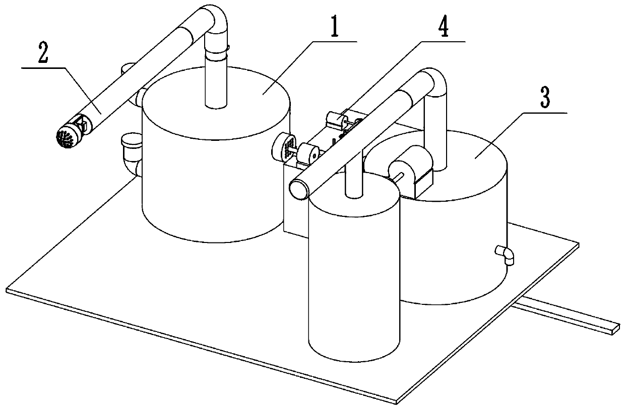
[0038] Combine below Figure 1-23 In this embodiment, an automatic gastric lavage device includes a liquid injection assembly 1, a gastroscope clamping assembly 2, a liquid suction assembly 3 and a power assembly 4, and the liquid injection assembly 1 is connected to the power assembly 4 , the gastroscope clamping assembly 2 is connected with the liquid injection assembly 1, and the liquid suction assembly 3 is connected with the power assembly 4.
specific Embodiment approach 2
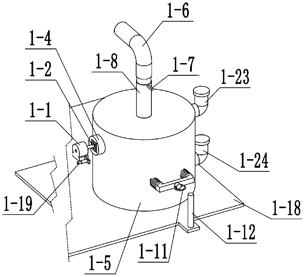
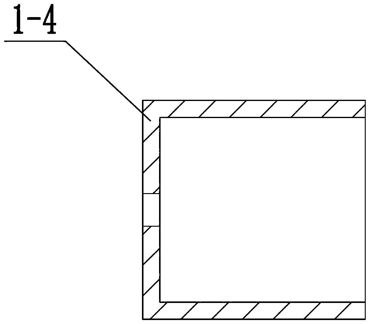
[0040] Combine below Figure 1-23 In this embodiment, an automatic gastric lavage device includes a liquid injection assembly 1 including a liquid injection motor 1-1, a liquid injection motor shaft 1-2, a liquid injection fan 1-3, a liquid injection fan cover 1-4, a liquid storage Chamber 1-5, outlet pipe 1-6, knob 1-7, threaded barrel 1-8, lower outlet pipe 1-9, partition 1-10, buckle 1-11, fixed column 1-12, pull Column 1-13, carriage 1-14, tension spring Ⅰ1-15, blocking plate 1-16, air hole 1-17, bottom plate 1-18, button 1-19, button slide 1-20, spring Ⅰ1-21 , switch bracket 1-22, upper liquid injection port 1-23 and lower liquid injection port 1-24, liquid injection motor 1-1 is connected with liquid injection motor shaft 1-2, liquid injection motor shaft 1-2 is connected with liquid injection The fans 1-3 are connected, the liquid injection motor shaft 1-2 is rotationally connected with the liquid injection fan cover 1-4, the liquid injection fan 1-3 is located in the ...
specific Embodiment approach 3
[0042] Combine below Figure 1-23 This embodiment, this embodiment will further explain Embodiment 1. The gastroscope clamping assembly 2 includes a rubber tube 2-1, a hard half tube 2-2, a side wall I2-3, a side wall II2-4, and clips. Slider 2-5, Spring II 2-6, Clip I 2-7, Clip II 2-8, Clip III Slide Rail 2-9, Clip III 2-10, Extension Spring II 2-11, Slide Rail Frame 2-12, Clip III Slide Groove 2-13, semicircular cover slide rail 2-14, semicircular cover 2-15 and hemispherical head 2-16, rubber hose 2-1 is connected with liquid outlet pipe 1-6, rubber hose 2-1 is connected with rigid half pipe 2- 2-phase connection, side wall Ⅰ2-3, side wall Ⅱ2-4 are connected with hard half pipe 2-2, clip slider 2-5 is connected with side wall Ⅱ2-4, spring Ⅱ2-6 is located in clip slider Inside 2-5, clip Ⅰ 2-7 is slidingly connected with clip sliding cylinder 2-5, clip Ⅱ 2-8 is connected with hard half pipe 2-2, clip Ⅲ slide rail 2-9 is slidably connected with clip Ⅲ 2-10, clip Ⅲ2-10 is sli...
PUM
 Abstract
Description
Claims
Application Information
 - R&D Engineer
- R&D Manager
- IP Professional
- Industry Leading Data Capabilities
- Powerful AI technology
- Patent DNA Extraction
Browse by: Latest US Patents, China's latest patents, Technical Efficacy Thesaurus, Application Domain, Technology Topic, Popular Technical Reports.
© 2024 PatSnap. All rights reserved.Legal|Privacy policy|Modern Slavery Act Transparency Statement|Sitemap|About US| Contact US: help@patsnap.com


