Eureka AIR delivers breakthrough ideas for toughest innovation challenges, trusted by R&D personnel around the world.

Block clearing device for combustion chamber negative pressure sampling pipeline

A furnace negative pressure and sampling tube technology, which is applied in the direction of cleaning hollow objects, cleaning methods and utensils, chemical instruments and methods, etc., can solve the problems of cumbersome procedures, personal risks, tripping, etc., and achieve the effect of simple operation

Pending Publication Date: 2019-10-18
华能沁北发电有限责任公司
View PDF0 Cites 4 Cited by
  • Summary
  • Abstract
  • Description
  • Claims
  • Application Information

AI Technical Summary

Problems solved by technology

[0002] Furnace negative pressure sampling devices in thermal power plants are prone to dust accumulation and cause large deviations in negative pressure fluctuations. If the pressure exceeds a certain level, the MFT will operate, causing the unit to trip, affecting the safe and stable operation of the unit.
At present, there are two ways to remove the blockage of the furnace negative pressure sampling pipeline: manual cleaning and pneumatic blowing; both need to go through corresponding procedures to remove the main protection and automatically induce air, and stabilize the load of the unit, the procedure is cumbersome
The end cover of the sampling pipe needs to be opened during manual cleaning, and the method of poking with thin steel bars is used to achieve the purpose of unclogging. During the operation, the unit is adjusted incorrectly, which may easily cause positive pressure in the furnace, causing flames to escape from the sampling pipe, which poses personal risks and is not conducive to the unit. Stable operation; Pneumatic purging cannot remove hardened ash. During normal sampling, if there is air leakage in the high-pressure gas source pipeline, it is easy to cause the negative pressure of the furnace to exceed the limit and trigger the MFT to cause a trip

Method used


Image

  • Block clearing device for combustion chamber negative pressure sampling pipeline
  • Block clearing device for combustion chamber negative pressure sampling pipeline
  • Block clearing device for combustion chamber negative pressure sampling pipeline

Examples


Embodiment

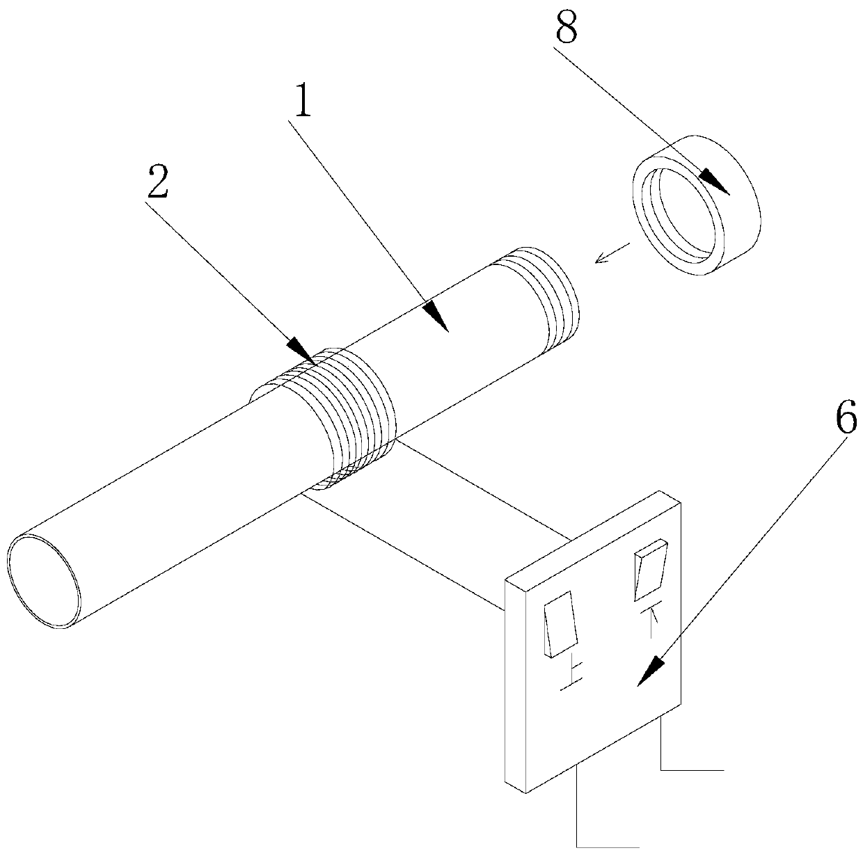
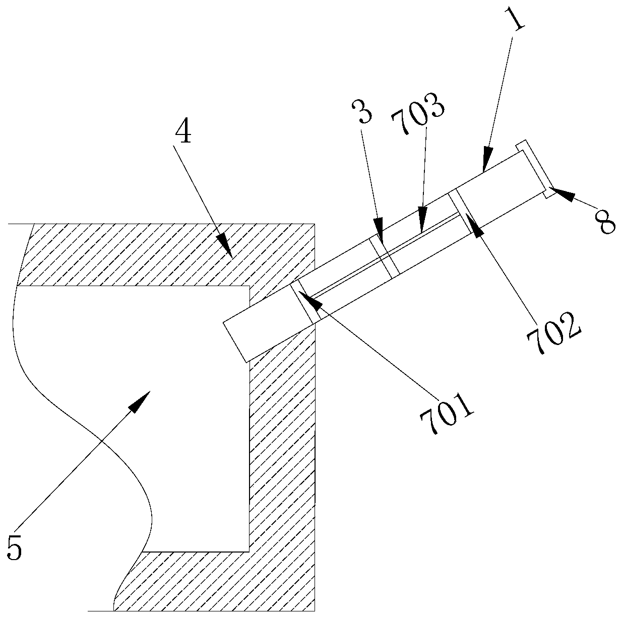
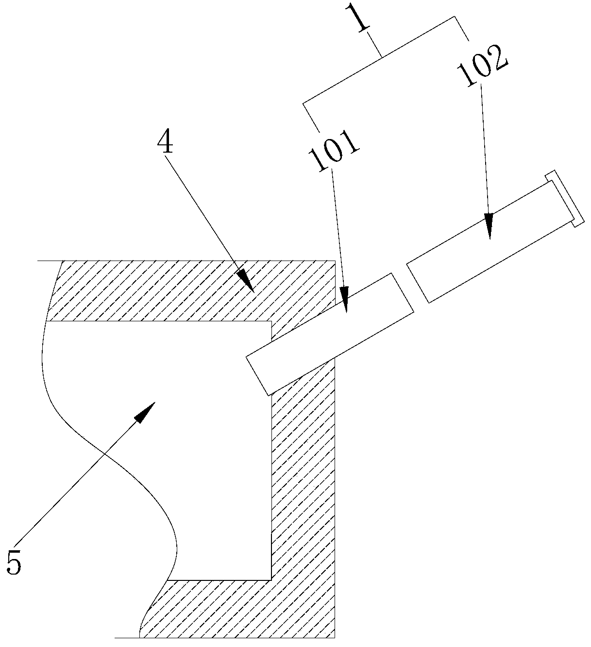
[0027] A furnace negative pressure sampling pipeline clearing device, please refer to the attached figure 1 - attached Figure 5 And shown in accompanying drawing-8, comprise sampling tube 1, coil 2, clearing assembly 7 and anti-falling frame 3, sampling tube 1 comprises inner sampling tube 101 and outer sampling tube 102, and one end of inner sampling tube 101 is inclined downwards and passes through Pass the insulation wall 4 and extend to the inside of the furnace 5, the other end of the inner sampling tube 101 is placed outside the insulation wall 4 and welded with one end of the outer sampling tube 102 to form a sampling tube 1 as a whole; the anti-falling frame 3 is welded to the inner sampling tube 101 and On the inner wall of the welding part of the outer sampling tube 102; the coil 2 is evenly wound on the outer wall of the middle part of the sampling tube 1, and the two ends of the coil 2 are electrically connected with the polarity switch 6; the polarity switch 6 an...


PUM


Abstract

The invention provides a block clearing device for a combustion chamber negative pressure sampling pipeline. The block clearing device comprises a sampling pipe, a coil, a block clearing assembly andan anti-falling frame, wherein the sampling pipe comprises an inner sampling pipe and an outer sampling pipe, one end of the inner sampling pipe downwards obliquely penetrates through a heat preservation wall and extends into a combustion chamber, and the other end of the inner sampling pipe is arranged outside the heat preservation wall and is welded with one end of the outer sampling pipe into awhole sampling pipe; the anti-falling frame is welded on the inner wall of a welding part between the inner sampling pipe and the outer sampling pipe; the coil is uniformly wound on the outer wall ofthe middle part of the sampling pipe, and the two ends of the coil are electrically connected with a polarity reversing switch; and the block clearing assembly is arranged inside the sampling pipe and can slide back and forth along the two ends of the sampling pipe, the block clearing assembly is provided with a first magnet and a second magnet in an embedded mode, and the opposite faces of the first magnet and the second magnet are in a same polarity. The block clearing device for the combustion chamber negative pressure sampling pipeline does not need to withdraw main protection, an end cover of the sampling pipe does not need to be opened, and the purpose of efficient block clearing of the sampling pipeline can be achieved no matter the load of the unit; and in addition, the normal sampling is not affected under a working and a stopping state, the stable operation of the unit is not affected, the device is not limited by time, and the operation is simple.

Description

technical field [0001] The invention relates to the field of pipeline blockage removal, in particular to a furnace negative pressure sampling pipeline blockage removal device. Background technique [0002] Furnace negative pressure sampling devices in thermal power plants tend to accumulate dust and cause large deviations in negative pressure fluctuations. If the pressure exceeds a certain level, the MFT will operate, causing the unit to trip, affecting the safe and stable operation of the unit. At present, there are two ways to clear the blockage of the furnace negative pressure sampling pipeline: manual cleaning and pneumatic blowing; both need to go through corresponding procedures to remove the main protection and automatically induce air, and stabilize the load of the unit, and the procedures are cumbersome. The end cover of the sampling pipe needs to be opened during manual cleaning, and the method of poking with thin steel bars is used to achieve the purpose of unclog...

Claims


Application Information

Patent Timeline
Patent Type & Authority Applications(China)
IPC IPC(8): B08B9/043
CPCB08B9/0436
Inventor 夏珺杨号宗刘萌吴呈余晓华季洪蒙
Owner 华能沁北发电有限责任公司
Why Eureka
Eureka Blog
Learn More