Residual liquid removing device

A residual liquid and liquid injection port technology, applied in the field of residual liquid removal devices, can solve the problems of high cost, low efficiency, large consumption of non-woven fabrics, etc., and achieve the effects of reducing production cost, easy waste liquid, and efficient cleaning

Pending Publication Date: 2020-06-09
WUXI LEAD INTELLIGENT EQUIP CO LTD
View PDF0 Cites 1 Cited by
  • Summary
  • Abstract
  • Description
  • Claims
  • Application Information

AI Technical Summary

Problems solved by technology

[0004] Based on this, in order to use the wiping method to clean the residual liquid of the liquid injection port of the lithium battery, the liquid injection port needs to be sealed first, and the sharp corner of the liquid injection port cannot be effectively cleaned, and there are problems of large consumption of non-woven fabrics, low efficiency and high cost. , providing a residual liquid removal device

Method used


Image

  • Residual liquid removing device
  • Residual liquid removing device
  • Residual liquid removing device

Examples


Embodiment 1

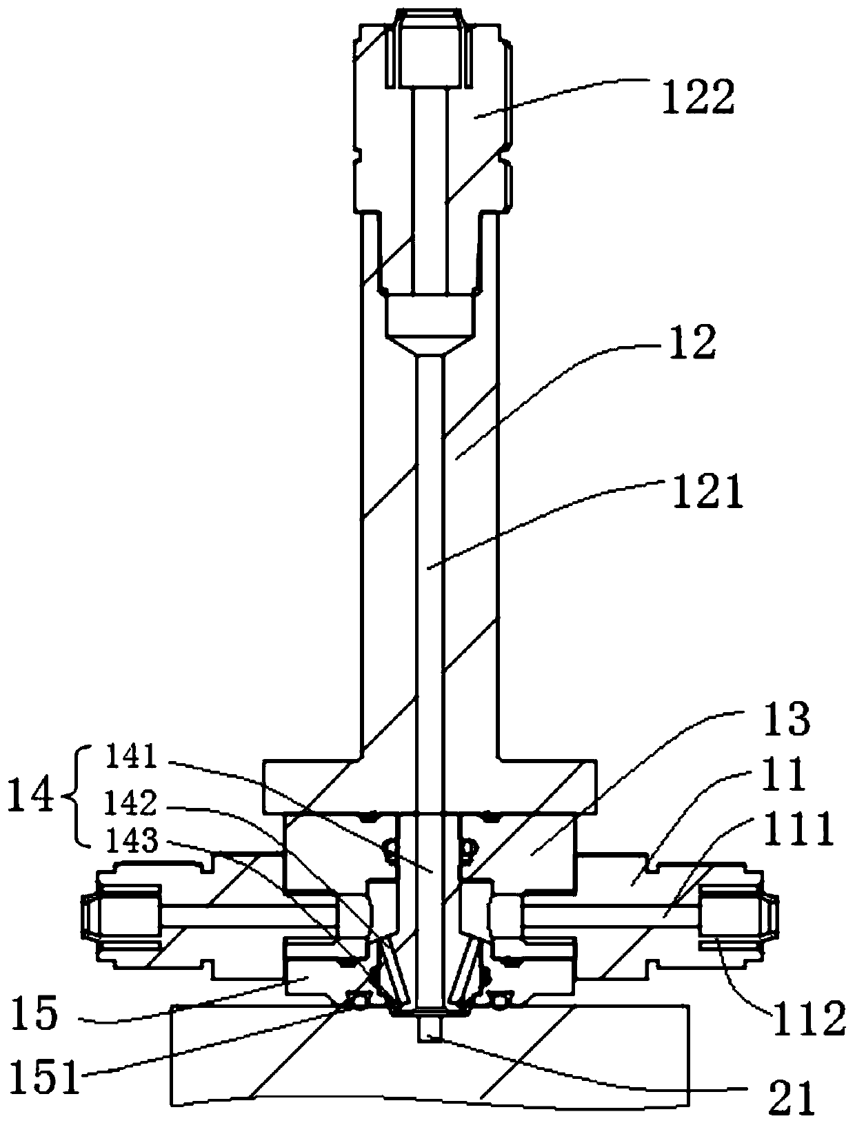
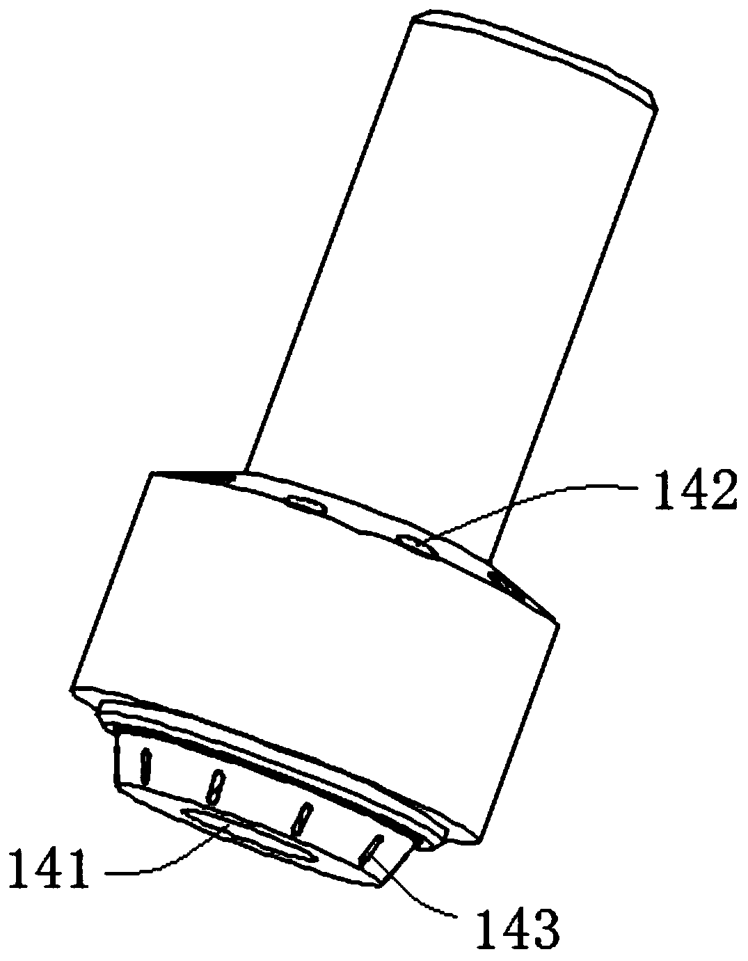
[0045]The cleaning head assembly 14 in the first embodiment is provided with a plurality of air ducts, specifically, including at least one first air duct 142 and at least one second air duct 143, the first air duct 142 and the second air duct 143 one by one Correspondingly connected, one end of the first air duct 142 communicates with the second air duct 143, and the other end communicates with the air intake pipe 11, and one end of the second air duct 143 abuts against the battery liquid injection port 21, so that the compressed air passes through the first The air channel 142 and the second air channel 143 spray on the liquid injection port 21 of the battery. In order to accelerate the compressed air passing through the first air passage 142 after entering the second air passage 143, the aperture of the first air passage 142 is larger than the aperture of the second air passage 143, and the first air passage 142 and the second air passage 143 If the first air duct 142 is ar...

Embodiment 5

[0057] The cleaning head assembly 54 provided in the fifth embodiment differs from the fourth embodiment in that a second air passage 542 and a third air passage 543 are respectively provided at the ends of the first air passage 541, and the second air passage 542 and the third air passage 543 The ends of the third air channel 543 are all in contact with the battery liquid injection port 21, so that the compressed air can be sprayed at the battery liquid injection port 21 from two directions, and the atomization effect is improved. It should be noted that the designer can choose a reasonable combination method according to actual needs, that is, the first air duct 541 can be combined with the second air duct 542 and the third air duct 543, or one of them can be combined, as long as it can Realizing the atomization effect is all allowed by this application.

[0058] The residual liquid removal device provided in Embodiments 3 to 5 includes at least one inlet pipe 11 (eight inle...


PUM


Abstract

The invention relates to a residual liquid removing device. The residual liquid removing device is used for cleaning a battery liquid injection port and comprises an air inlet pipe, an exhaust pipe and a cleaning head assembly, wherein the exhaust pipe communicates with the battery liquid injection port; and the cleaning head assembly comprises at least one air duct, one end of the air duct is connected with the air inlet pipe, and the other end of the air duct abuts against the battery liquid injection port. According to the residual liquid removing device, compressed air is introduced to thecleaning head assembly, a high-pressure air flow is sprayed to the battery liquid injection port and atomizes the residual liquid at the liquid injection port by using the at least one air duct on the cleaning head assembly, and then the atomized electrolyte residual liquid is pumped away by using an air pumping device, so that the purpose of removing the residual liquid is achieved. By adoptingthe residual liquid removing device, no pollution is caused, and waste gas and waste liquid are easy to recycle; and residues in an electrolyte injection hole can be efficiently cleared, no consumables and no material replacement are needed in the cleaning process, the production cost is effectively reduced, the purpose of rapid and efficient cleaning is finally achieved, and the requirement for 24-hour unmanned operation is further met.

Description

technical field [0001] The invention relates to the technical field of battery production equipment, in particular to a residual liquid removal device. Background technique [0002] After the lithium battery is filled with electrolyte and sealed, there will be residue in the liquid injection port, which will cause contamination of the liquid injection port. The traditional method is to use the method of wiping non-woven fabrics for treatment, but the liquid injection port of the battery is generally equipped with steps, and the method of wiping cannot effectively clean the sharp corners of the steps, and the removal effect is not ideal, and non-woven fabrics are consumables. Frequent replacement, low efficiency and high cost. In addition, under normal circumstances, lithium batteries need to be injected twice. The first injection needs to inject electrolyte into the battery, and the second injection is to replenish the electrolyte after the first injection. After the liqui...

Claims


Application Information

Patent Timeline
Patent Type & Authority Applications(China)
IPC IPC(8): B08B5/02B08B15/04
CPCB08B5/02B08B15/04
Inventor 不公告发明人
Owner WUXI LEAD INTELLIGENT EQUIP CO LTD
Why Eureka
Try Eureka