
A micropump controlled and driven by a single valve

A valve control, a single technology, applied to pumps with flexible working elements, parts of pumping devices for elastic fluids, pumps, etc., can solve the problems of limiting the scope of application, unable to establish back pressure, etc., and achieve simple structure , high consistency, and the effect of simplifying the preparation process

Active Publication Date: 2020-05-15
SHANGHAI JIAOTONG UNIV
View PDF4 Cites 0 Cited by
  • Summary
  • Abstract
  • Description
  • Claims
  • Application Information

AI Technical Summary

Problems solved by technology

Although this valveless driving method with the contraction / expansion port structure can also realize the one-way drive of the fluid, but because the inlet and the outlet are connected, it is impossible to establish a back pressure. This defect greatly limits its scope of application

Method used

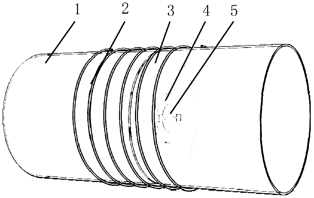
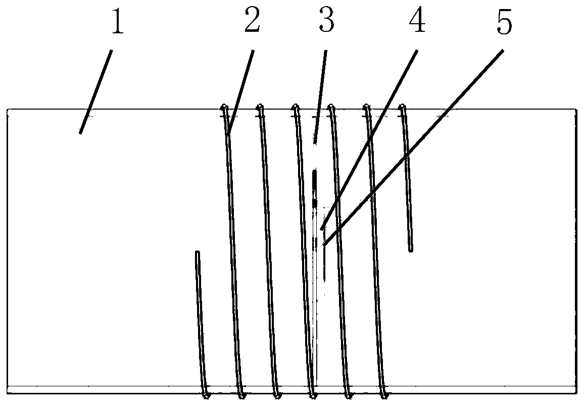
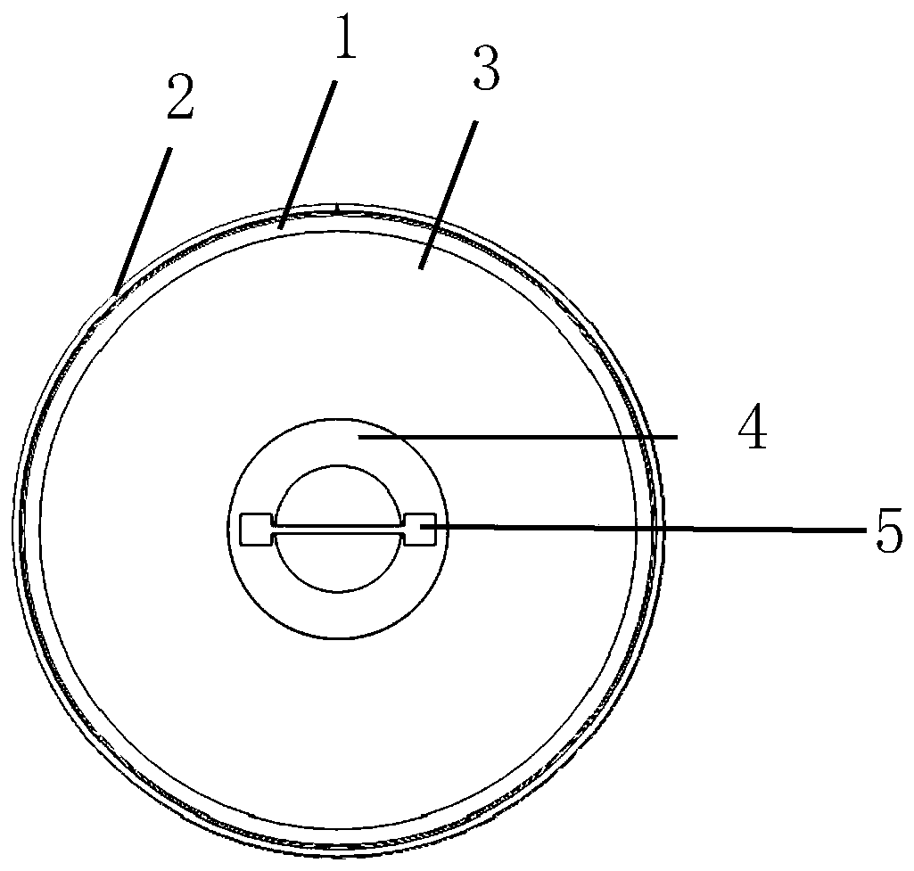

Image

  • A micropump controlled and driven by a single valve
  • A micropump controlled and driven by a single valve
  • A micropump controlled and driven by a single valve

Examples


Embodiment Construction

[0047] In the following description, the present invention will be described with reference to various embodiments. However, those skilled in the art will recognize that the various embodiments can be implemented without one or more specific details or with other alternative and / or additional methods, materials or components. In other cases, well-known structures, materials, or operations are not shown or described in detail so as not to obscure aspects of various embodiments of the present invention. Similarly, for the purpose of explanation, specific quantities, materials, and configurations are set forth in order to provide a thorough understanding of the embodiments of the present invention. However, the present invention can be implemented without specific details. In addition, it should be understood that the various embodiments shown in the drawings are illustrative representations and are not necessarily drawn to scale.

[0048] In this specification, reference to "one ...


PUM


Abstract

The invention discloses a single valve controlled and driven micro pump. The single valve controlled and driven micro pump comprises a varying magnetic field generating device, an elastic film, a magnetic plate with an opening in a center, and a valve plate, wherein the varying magnetic field generating device is arranged on the outer wall of a pipeline and generates varying magnetic fields; the shape of the periphery of the elastic film is the same with that of the section of the inner wall of the pipeline, and the elastic film is sealed and fixed on the inner wall of the pipeline; the magnetic plate is fixed on the middle part of the elastic film, and the periphery of the magnetic plate is connected to the elastic film, and the opening of the magnetic plate is not covered by the elasticfilm; and the valve plate is fixed on the magnetic plate, and covers the opening of the magnetic plate.

Description

Technical field [0001] The field of the invention belongs to the technical field of electromagnetically driven mechanical displacement micropumps, and specifically relates to a micropump that can control and directionally drive microfluidics under electromagnetic drive and only requires a single valve. Background technique [0002] Microfluidic system is a system that controls, manipulates and detects complex fluids in microscopic dimensions. It is an interdisciplinary subject developed based on microelectronics, micromechanics, bioengineering, and nanotechnology. The function realization of the microfluidic system depends on its integrated functional components, such as micropumps, microvalves, micromixers, microreactors, microdetectors, and microsensors. The operating fluid is the foundation and key of the entire system, which relies on the micropump. [0003] According to the working principle, it can generally be divided into mechanical displacement micro pump and non-mechanic...

Claims


Application Information

Patent Timeline
Patent Type & Authority Patents(China)
IPC IPC(8): F04B43/04F04B53/10
CPCF04B43/043F04B53/102
Inventor 丁桂甫唐智勇姚锦元黄建泽邵秀锋周文文
Owner SHANGHAI JIAOTONG UNIV
Learn More