Heat energy recovery system

A heat energy recovery and heat energy technology, applied in heat recovery systems, energy recovery systems for ventilation and heating, air conditioning systems, etc. The effect of reducing energy loss and avoiding excessive cotton dust particles

Active Publication Date: 2019-10-18
武汉裕大华纺织服装集团有限公司
View PDF14 Cites 0 Cited by
  • Summary
  • Abstract
  • Description
  • Claims
  • Application Information

AI Technical Summary

Problems solved by technology

[0007] In order to solve the problem that heat energy is not utilized in the design of the above-mentioned air-conditioning system and dust removal system of the traditional textile mill, but is directly discharged into the atmosphere, which not only aggravates the greenhouse effect and causes environmental pollution, but also causes energy waste. The purpose of the present invention is to provide A heat energy recovery system, through the mixed pretreatment of the air volume of the fresh air system and the dust removal heat energy recovery system. After the surface cooling treatment, it enters the air conditioning room for cooling or heating treatment. The excess heat energy is sent to the return air system through the air supply pipe, and the heat energy is circulated to the return air window through the primary return air device and the secondary return air device in the return air system. , to achieve the purpose of heat recovery

Method used


Image

  • Heat energy recovery system
  • Heat energy recovery system
  • Heat energy recovery system

Examples


Embodiment 1

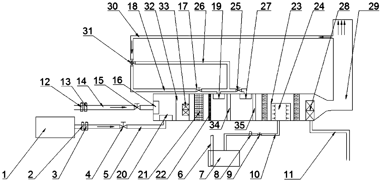
[0031] A heat energy recovery system, including a fresh air system, a return air system, a dust removal heat recovery system, a filter system and an air conditioning system; the five systems are connected through an air volume regulating valve and passages, and the air volume of the fresh air system, the return air system, and the dust removal heat energy are recovered The air volume of the system, the wind energy is mixed and preheated by the fresh air system and the dust removal heat energy recovery system, then enters the filter system for filtration, and after filtration, it is mixed with the wind energy of the return air system and enters the air conditioning system. The return air system sends all the way to the room to complete cooling or heating.

[0032] Further, the fresh air system includes a fresh air humidity tester 12, a fresh air temperature tester 13, and a fresh air window air volume regulating valve 15. The fresh air system performs humidity and temperature test...

Embodiment 2

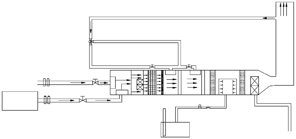
[0042] figure 2 It is a schematic diagram of the flow of heat energy recovered from dust removal heat energy in the present invention, figure 2 The fresh air wind energy in the central fresh air system is tested and analyzed by the fresh air humidity tester 12 and the fresh air temperature tester 13, and the air volume is adjusted by adjusting the fresh air window air volume regulating valve 15 and enters the fresh air window 16 through the fresh air pipe 14; the dust removal unit 1 performs dust removal operation Finally, the thermal energy after dedusting is tested and analyzed by the dedusting thermal energy temperature tester 2 and the dedusting thermal energy humidity tester 3, and the dedusting thermal energy air volume control valve 4 is adjusted through the dedusting wind energy pipeline 5 to enter the dedusting thermal energy return wind window 20; 16 and the dust removal heat energy return window 20 heat energy enters the mixing preheating chamber 32, and the fresh...


PUM


Abstract

The invention provides a heat energy recovery system, and belongs to the technical field of energy recovery. The heat energy recovery system comprises a fresh air system, an air return system, a dustremoval heat energy recovery system and a filtering system; the fresh air system comprises a fresh air humidity tester, a fresh air temperature tester and a fresh air window air volume adjusting valve; the air return system comprises a primary air return device and a secondary air return device; the dust removal heat energy recovery system comprises a dust removal unit, a dust removal heat energytemperature tester, a dust removal heat energy humidity tester and a dust removal heat energy air volume adjusting valve; and the filtering system comprises a primary filtration system and a secondaryfiltration system. The air volume of the fresh air system and the dust removal heat energy recovery system is subjected to mixing pretreatment, and then enters an air conditioning chamber for refrigeration or heating treatment after being filtered by a filtration system and subjected to surface treatment with an air return system, redundant heat energy is sent to the air return system through theair supply pipeline, and the heat energy is recycled to the air return window through the air return system again, so that the purpose of heat energy recovery is achieved.

Description

technical field [0001] The invention belongs to the technical field of energy recovery, and in particular relates to a heat energy recovery system. Background technique [0002] With the rapid development of urbanization and industrialization in our country, industrial energy consumption is high and energy utilization rate is low. Among them, the textile industry is one of the main energy-consuming industries in my country, and the phenomenon of energy waste is serious. Under the situation of continuous improvement and increasing competition pressure, it is particularly important to choose reasonable and efficient energy-saving and emission-reduction technologies to apply to production workshops, reduce energy expenses of enterprises, and enable energy to be used effectively. [0003] In the textile production process, due to differences in production processes and production equipment, heat imbalances in different workshops often occur. Usually, due to the lack of heating eq...

Claims


Application Information

Patent Timeline
Patent Type & Authority Applications(China)
IPC IPC(8): F24F12/00F24F13/28F24F11/89F24F11/84F24F13/02
CPCF24F12/00F24F13/02F24F13/28F24F11/84F24F11/89Y02B30/56
Inventor 田青吕继平张义平卢丽平
Owner 武汉裕大华纺织服装集团有限公司
Why Eureka
Try Eureka