Refractory wash bonding time tester and testing method

A technology of time tester and refractory mud, which is applied in the direction of instruments, measuring devices, scientific instruments, etc., can solve the problems of large influence on test results, torsional slip dislocation, poor precision, etc., and achieve simple test methods and accurate test results high effect

Active Publication Date: 2019-10-18
中冶武汉冶金建筑研究院有限公司
View PDF7 Cites 2 Cited by
  • Summary
  • Abstract
  • Description
  • Claims
  • Application Information

AI Technical Summary

Problems solved by technology

The test process is judged and controlled by artificial feeling, the accuracy is poor, and it is easy to produce torsional slip dislocation, and the test results are greatly affected by human factors

Method used


Image

  • Refractory wash bonding time tester and testing method
  • Refractory wash bonding time tester and testing method

Examples


Embodiment 1

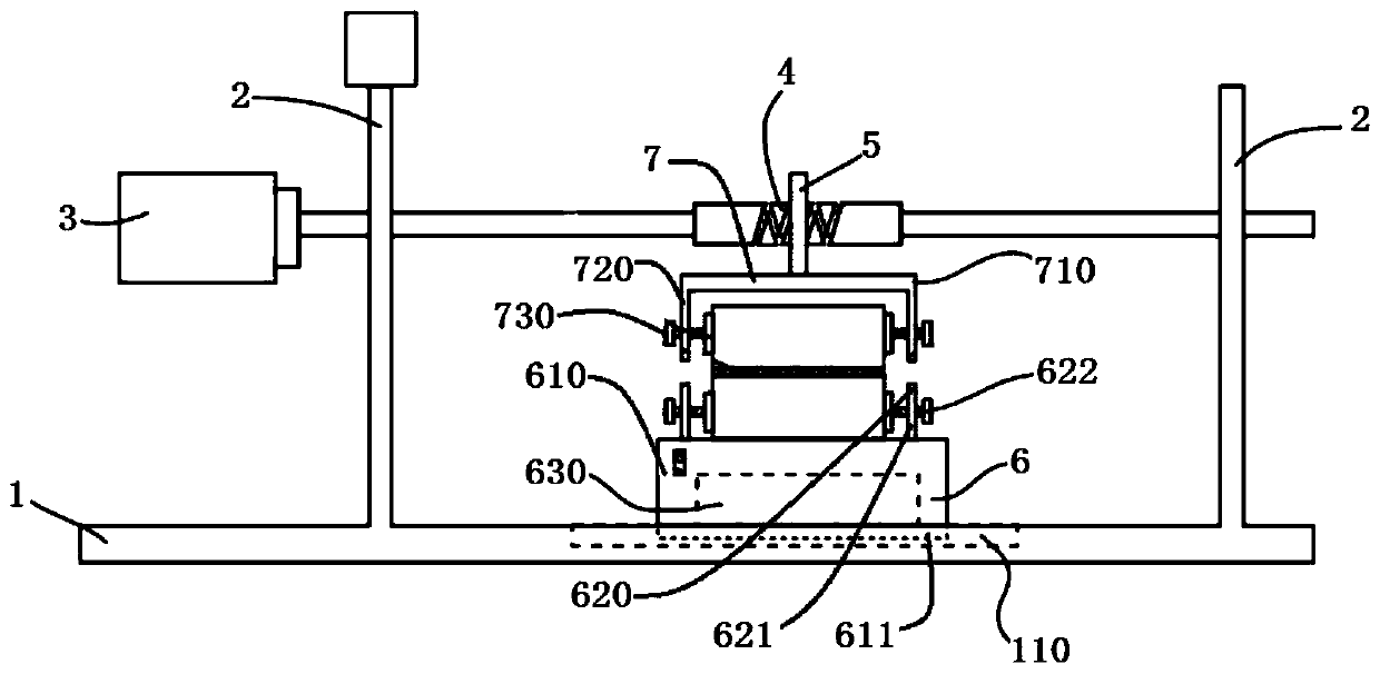
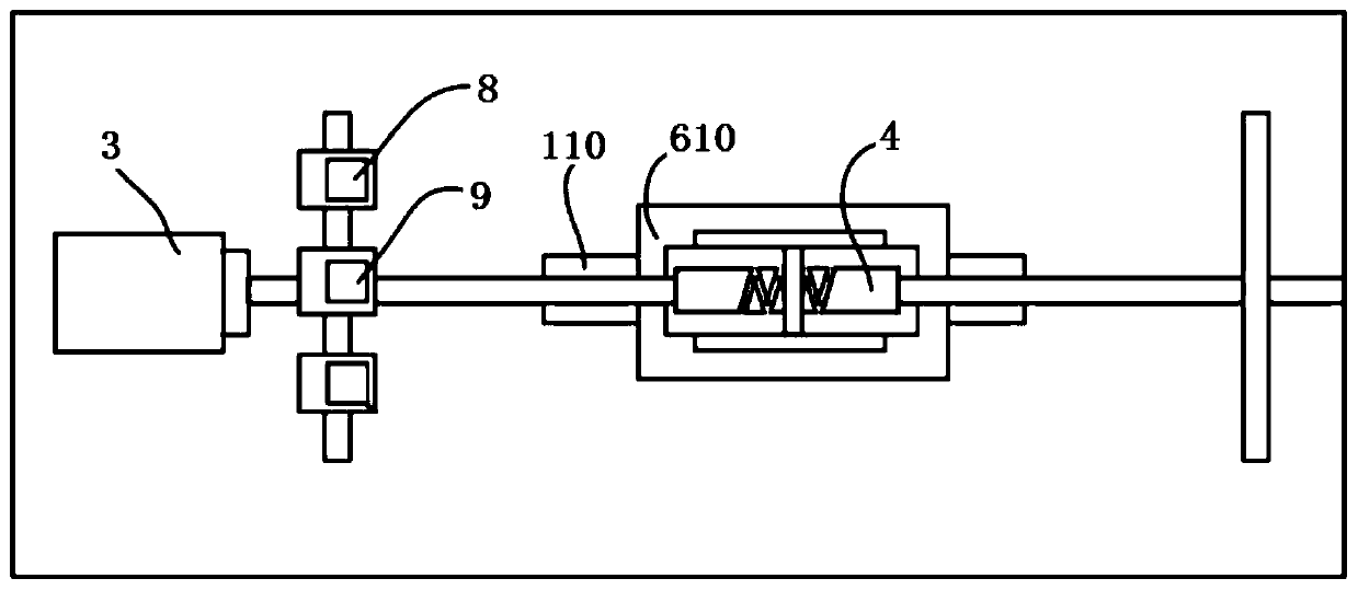
[0029] Such as figure 1 , figure 2 As shown, a refractory mud bonding time tester includes a base plate 1, a support frame 2, a servo motor 3, a reciprocating screw rod 4, a slider 5, a bearing seat 6, a mechanical claw 7, a force measuring device 8 and a timer 9 . Bearing seat 6 is arranged on the upper end face of base plate 1, and base plate 1 is respectively provided with a supporting frame 2 on both sides of bearing seat 6, and the two ends of reciprocating screw rod 4 are respectively connected with two supporting frames 2 in rotation, and reciprocating screw rod 4. It is preferably located directly above the bearing seat 6. The servo motor 3 is arranged on the support frame 2 or the bottom plate 1. The output shaft of the servo motor 3 is connected with one end of the reciprocating screw rod 4, that is, the servo motor 3 can drive the reciprocating The screw mandrel 4 rotates; the reciprocating screw mandrel 4 between the two support frames 2 is provided with a slide...

Embodiment 2

[0031] Such as figure 1 , figure 2 As shown, a refractory mud bonding time tester includes a base plate 1, a support frame 2, a servo motor 3, a reciprocating screw rod 4, a slider 5, a bearing seat 6, a mechanical claw 7, a force measuring device 8 and a timer 9 . Bearing seat 6 is arranged on the upper end face of base plate 1, and base plate 1 is respectively provided with a supporting frame 2 on both sides of bearing seat 6, and the two ends of reciprocating screw rod 4 are respectively connected with two supporting frames 2 in rotation, and reciprocating screw rod 4. It is preferably located directly above the bearing seat 6. The servo motor 3 is arranged on the support frame 2 or the bottom plate 1. The output shaft of the servo motor 3 is connected with one end of the reciprocating screw rod 4, that is, the servo motor 3 can drive the reciprocating The screw mandrel 4 rotates; the reciprocating screw mandrel 4 between the two support frames 2 is provided with a slide...

Embodiment 3

[0034] Such as figure 1 , figure 2 As shown, a refractory mud bonding time tester includes a base plate 1, a support frame 2, a servo motor 3, a reciprocating screw rod 4, a slider 5, a bearing seat 6, a mechanical claw 7, a force measuring device 8 and a timer 9 . Bearing seat 6 is arranged on the upper end face of base plate 1, and base plate 1 is respectively provided with a supporting frame 2 on both sides of bearing seat 6, and the two ends of reciprocating screw rod 4 are respectively connected with two supporting frames 2 in rotation, and reciprocating screw rod 4. It is preferably located directly above the bearing seat 6. The servo motor 3 is arranged on the support frame 2 or the bottom plate 1. The output shaft of the servo motor 3 is connected with one end of the reciprocating screw rod 4, that is, the servo motor 3 can drive the reciprocating The screw mandrel 4 rotates; the reciprocating screw mandrel 4 between the two support frames 2 is provided with a slide...


PUM


Abstract

The invention discloses a refractory wash bonding time tester and testing method. The refractory wash bonding time tester includes a bottom plate, support frames, a servo motor, a reciprocating screwrod, a sliding block, a bearing seat, a mechanical claw, a force measuring device, and a timer; the bearing seat is disposed on the upper end surface of the bottom plate; a support frame is arranged on each side of the bottom plate, and the reciprocating screw rod is rotatably connected to the two support frames; the servo motor is disposed on the support frames, and the output shaft is connectedto one end of the reciprocating screw rod; the sliding block is arranged on the reciprocating screw; the mechanical claw is fixed under the sliding block to drive the reciprocating motion of an upperrefractory brick; a clamping assembly for clamping a lower refractory brick is disposed on the bearing seat; and the force measuring device and the timer are electrically connected to the servo motorseparately. During a test, the servo motor drives the reciprocating screw rod to rotate, thereby driving the upper refractory brick to reciprocate to determine the bonding time of the refractory wash.The beneficial effects of the invention are as follows: the horizontal traction force can be measured, the time can be measured synchronously, the artificial influence in the test is eliminated, andthe test accuracy is improved.

Description

technical field [0001] The invention relates to the technical field of refractory material detection, in particular to a refractory mud bonding time tester and method. Background technique [0002] The bonding time of refractory mud is an important index to measure the performance of refractory mud. It is related to the efficiency of refractory mud construction and masonry, and even determines whether refractory mud can be used. The current international standard ISO13765.3 adopts the method of bonding the refractory mud and refractory brick masonry, and manually pushing the refractory brick until it cannot be pushed, so as to measure the bonding time of the refractory mud. The test process is judged and controlled by artificial feeling, the accuracy is poor, and it is easy to produce torsional slip dislocation, and the test results are greatly affected by human factors. Contents of the invention [0003] The technical problem to be solved by the present invention is to p...

Claims


Application Information

Patent Timeline
IPC IPC(8): G01N19/04G01N11/00
CPCG01N19/04G01N11/00
Inventor 伍书军谢大勇程水明彭云涛夏昌勇冷永波吴龙水彭艳
Owner 中冶武汉冶金建筑研究院有限公司
Why Eureka
Try Eureka