Electric power monitoring device

A power monitoring and first-line technology, which is applied in the field of power monitoring devices, can solve problems such as the inability to monitor each power supply branch, and achieve the effects of saving wiring workload and layout space, simplifying installation, and reducing wiring workload

Pending Publication Date: 2019-10-18
JIANGSU SFERE ELECTRIC
View PDF0 Cites 2 Cited by
  • Summary
  • Abstract
  • Description
  • Claims
  • Application Information

AI Technical Summary

Problems solved by technology

Due to reasons such as size and cost, the existing monitoring schemes generally only monitor the main power supply circuit, but cannot monitor each power supply branch

Method used


Image

  • Electric power monitoring device
  • Electric power monitoring device
  • Electric power monitoring device

Examples


Embodiment Construction

[0035] In order to make the objectives, technical solutions, and advantages of the embodiments of the present invention clearer, the technical solutions in the embodiments of the present invention will be described clearly and completely in conjunction with the accompanying drawings in the embodiments of the present invention. Obviously, the described embodiments It is a part of the embodiments of the present invention, not all the embodiments. Based on the embodiments of the present invention, all other embodiments obtained by those of ordinary skill in the art without creative work shall fall within the protection scope of the present invention.

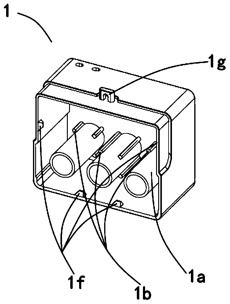
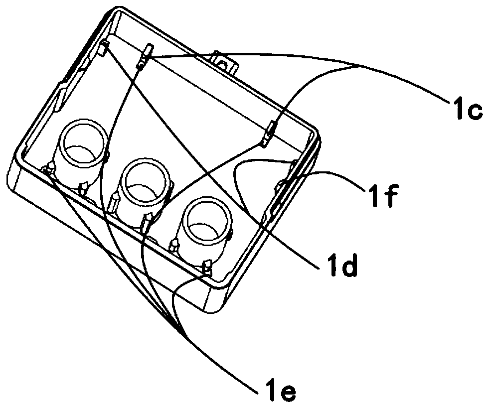
[0036] As shown in Figure 1(a)-(b), the inner surface of the first housing 1 is provided with a tube body 1a covering the transformer coil 4, a total of three are arranged in a line, and the outer ring of the tube body 1a is arranged in the circumferential direction There are support ribs 1b for supporting the coil 4 of the transforme...


PUM


Abstract

The invention relates to an electric power monitoring device, wherein the inner surface of a first casing is provided with a plurality of tube bodies, and the outer side of the top of the first casingis provided with a lead seal snap; the top of the inner side of a second casing is provided with a clamping groove for fixedly positioning a second circuit board, the outer surface of the second casing is provided with a guide groove for mounting a protective cover and equipped with perforations corresponding to the plurality of tube bodies; the top of the protective cover is provided with a leadseal ring and the inner side of the protective cover is provided with guide ribs; a first circuit board and the second circuit boards are electrically connected by a connector and perpendicular to each other. A transformer coil is mounted on the first circuit board, and electrically connected to the first circuit board. The first circuit board is provided with perforations corresponding to the tube bodies. The perforations of the first circuit board and the transformer coil are sequentially sleeved on the corresponding pipe body, the first circuit board is mounted on the inner surface of thefirst casing, and the second circuit board is mounted on the inner side face of the first casing The second casing is fixedly connected with the first casing. The guide ribs are inserted into the guiding groove, and the lead seal ring is fastened to the lead seal snap.

Description

Technical field [0001] The present invention relates to the technical field of power monitoring, in particular to a power monitoring device. Background technique [0002] In recent years, my country has implemented energy saving and consumption reduction as a major national policy, and the acquisition of electric energy data is the main source of energy data analysis. In order to achieve refined energy management and reduce costs and increase efficiency for enterprises, it is necessary to implement real-time monitoring of power data for each power supply loop or device. Existing monitoring schemes generally only monitor the main power supply circuit due to reasons such as size and cost, and cannot monitor each power supply branch. Summary of the invention [0003] In view of the problems and deficiencies in the prior art, the present invention provides a new type of power monitoring device. [0004] The present invention solves the above technical problems through the following te...

Claims


Application Information

Patent Timeline
Patent Type & Authority Applications(China)
IPC IPC(8): G01R31/00G01R19/00G01R15/18
CPCG01R31/00G01R19/00G01R15/18G01R22/065
Inventor 张凤雏顾益刚许文专朱君昌
Owner JIANGSU SFERE ELECTRIC
Why Eureka
Try Eureka