Method and projection system for realizing wave effect in static pattern projection
A technology of static pattern and projection system, applied in the field of projection, can solve the problem of unable to realize the dynamic fluctuation effect of the image plane, and achieve the effect of maintaining the clarity and changing the similarity
- Summary
- Abstract
- Description
- Claims
- Application Information
AI Technical Summary
Problems solved by technology
Method used
Image

Examples
Embodiment 1
[0050] This embodiment provides a method for realizing the wave effect of static pattern projection. By making the magnification ratios of the adjacent positions of the imaging object projected on the image plane different, the projection imaging of the image plane will produce a distortion effect, and at the same time, the magnification of different positions will be dynamically adjusted. Even if the image plane projection has dynamic optical distortion, the projection of the imaged object on the image plane will show a wave effect.
[0051] The dynamic adjustment of the magnification of different positions specifically includes: changing the magnification of a certain position to the magnification of an adjacent position.
[0052] The change of the magnification can change the distortion state of the image plane projection. In this scheme, the magnification of each position of the image plane projection is different to deform the image plane projection, and then dynamically a...
Embodiment 2
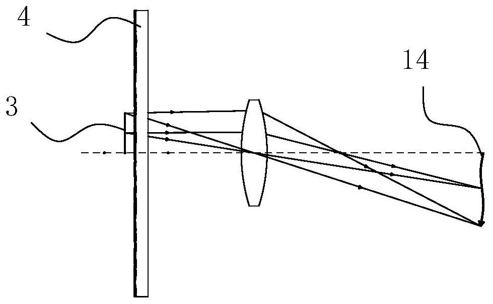
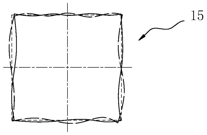
[0058] figure 1 It is a schematic diagram of the imaging principle of the projection system that realizes the wave effect of static pattern projection described in the embodiment of this solution, figure 2 It is a comparison diagram of the overlapping state of the projection effect of the rectangular imaging object after the optical distortion occurs and before the optical distortion occurs in the embodiment of the solution. Such as figure 1 , 2 As shown, this embodiment provides a projection system that realizes the wave effect of static pattern projection, which adds a disturbing sheet lens on the basis of the existing optical projection equipment, and through the structural design of the disturbing lens 4 and the relationship between the disturbing lens 4 and the imaging object The relative position change of 3 controls the imaging optical distortion state on the image plane 14 .
[0059] In this embodiment, a rectangular imaging object is taken as an example, figure ...
Embodiment 3
[0070] The solution of this embodiment is basically the same as that of Embodiment 2, the main difference lies in the shape of the disturbing lens 4 . Image 6 Another structural schematic diagram of the perturbation lens, Figure 7 for Image 6 Schematic enlarged cross-section of the perturbation mirror shown. Such as Image 6 , 7 As shown, the disturbance lens 4 in this embodiment is also circular, but the configuration of the arc-shaped convex surface 6 on it is different from that in the second embodiment.
[0071] Specifically, the perturbation lens 4 in this embodiment is formed by a plurality of curved convex surfaces 6 with optional free-form surface discontinuous transition between 6-150 mm in radius of curvature R, which are distributed in an array on the surface of the transparent glass, so The height H of the arc-shaped convex surface 6 changes continuously between 0.05-1.5mm. The arc-shaped convex surface 6 of the disturbing lens 4 is set toward the imaging o...
PUM
| Property | Measurement | Unit |
|---|---|---|
| Beam angle | aaaaa | aaaaa |
| Focal length | aaaaa | aaaaa |
| Height | aaaaa | aaaaa |
Abstract
Description
Claims
Application Information
 - R&D
- Intellectual Property
- Life Sciences
- Materials
- Tech Scout
- Unparalleled Data Quality
- Higher Quality Content
- 60% Fewer Hallucinations
Browse by: Latest US Patents, China's latest patents, Technical Efficacy Thesaurus, Application Domain, Technology Topic, Popular Technical Reports.
© 2025 PatSnap. All rights reserved.Legal|Privacy policy|Modern Slavery Act Transparency Statement|Sitemap|About US| Contact US: help@patsnap.com