

Method for quickly evaluating sound insulation performance of ship bulkhead structure
A bulkhead and sound insulation technology, which is applied in ship construction, ship parts, ships, etc., can solve the problems of increased material cost, design waste, and inability to accurately judge the sound insulation performance of bulkhead structures, etc., and achieve great significance, reduce design and The effect of manufacturing costs
- Summary
- Abstract
- Description
- Claims
- Application Information
AI Technical Summary
Benefits of technology
Problems solved by technology
Method used
Image

Examples
Embodiment Construction
[0031] The following will clearly and completely describe the technical solutions in the embodiments of the present invention with reference to the accompanying drawings in the embodiments of the present invention. Obviously, the described embodiments are only some, not all, embodiments of the present invention. Based on the embodiments of the present invention, all other embodiments obtained by persons of ordinary skill in the art without making creative efforts belong to the protection scope of the present invention.
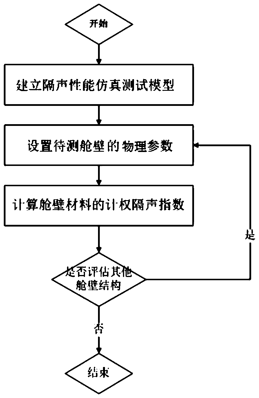
[0032] Such as figure 1 As shown, this embodiment provides a rapid evaluation method for the sound insulation performance of ship bulkhead structures, including the following three steps:
[0033] Step 1. Establish a sound insulation performance simulation test model;
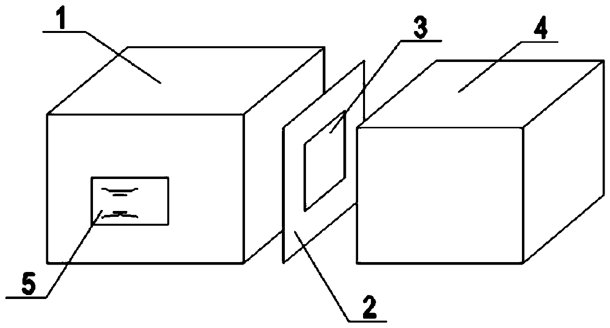
[0034] Such as figure 2 As shown, the sound insulation performance simulation test model is established in the acoustic software VA One, the model includes the sound source room 1, the recei...
PUM
 Abstract
Description
Claims
Application Information