An optical fingerprint sensor and display

A sensor and display technology, which is used in the acquisition/organization of fingerprints/palmprints, instruments, characters and pattern recognition, etc., can solve the problems of the thickness of the fingerprint sensor in the fingerprint sensing area, the limitations and other problems, to avoid Limitations, the effect of expanding the area

Active Publication Date: 2022-04-01
HKC CORP LTD +1
View PDF5 Cites 0 Cited by
  • Summary
  • Abstract
  • Description
  • Claims
  • Application Information

AI Technical Summary

Problems solved by technology

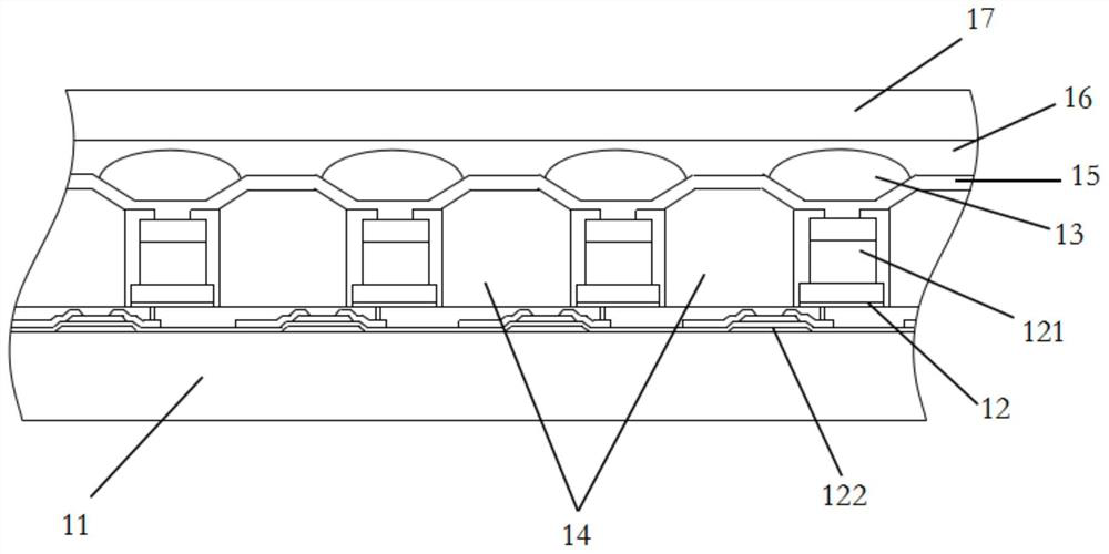
[0003] The main purpose of this application is to propose an optical fingerprint sensor, which aims to solve the problem that the sensing area of ​​the fingerprint in the prior art is limited by the thickness of the fingerprint sensor

Method used


Image

  • An optical fingerprint sensor and display
  • An optical fingerprint sensor and display
  • An optical fingerprint sensor and display

Examples


Embodiment Construction

[0020] The following will clearly and completely describe the technical solutions in the embodiments of the present application with reference to the accompanying drawings in the embodiments of the present application. Obviously, the described embodiments are only part of the embodiments of the present application, not all of them. Based on the embodiments in this application, all other embodiments obtained by persons of ordinary skill in the art without creative efforts fall within the protection scope of this application.

[0021] It should be noted that all directional indications (such as up, down, left, right, front, back...) in the embodiments of the present application are only used to explain the relationship between the components in a certain posture (as shown in the drawings). Relative positional relationship, movement conditions, etc., if the specific posture changes, the directional indication will also change accordingly. In addition, the descriptions involving "...


PUM

PropertyMeasurementUnit
thicknessaaaaaaaaaa

Abstract

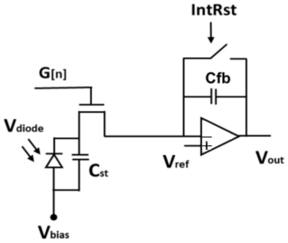
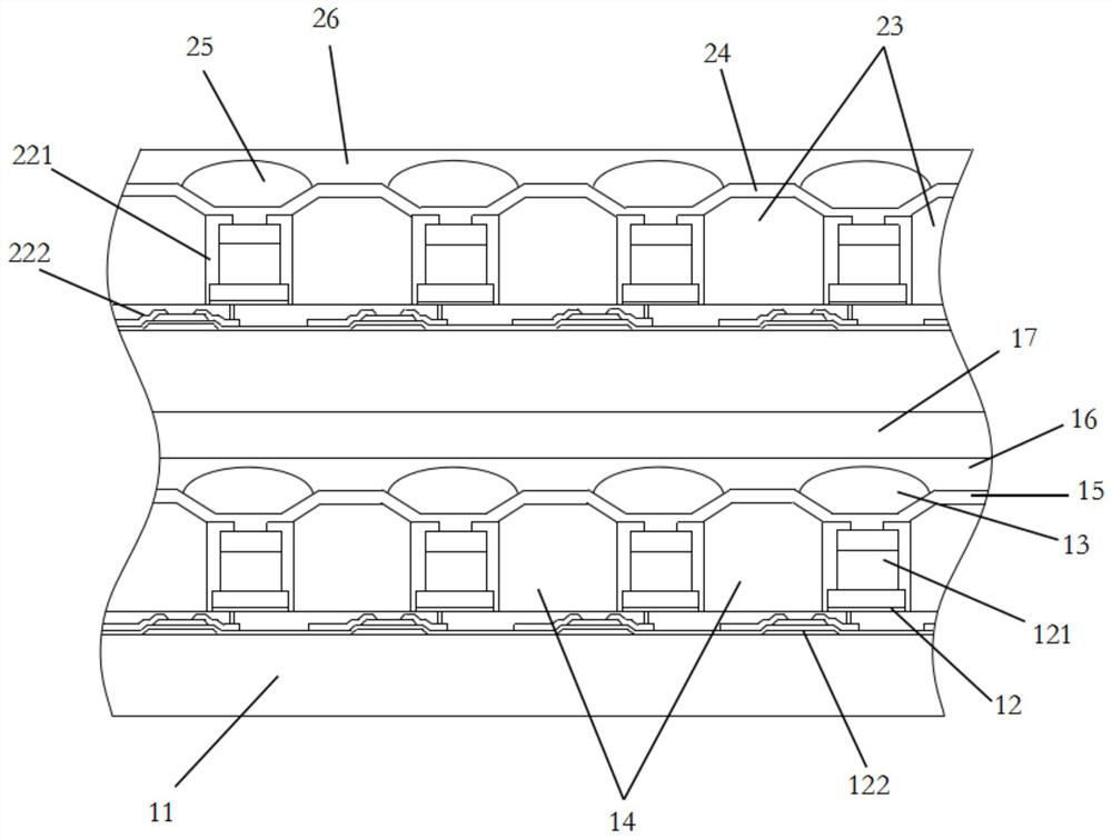
The present application discloses an optical fingerprint sensor, which includes: a first substrate; a plurality of sensor units arranged on the first substrate, the sensor units include photodiodes and electrodes connected to the photodiodes A connected thin film transistor; a first optical layer, disposed on the plurality of sensor units, including a plurality of convex lenses disposed opposite to the photosensitive diodes, so as to focus light to the photosensitive diodes. The application also discloses a display screen. The optical fingerprint sensor provided by the present application can expand the area infinitely without increasing the thickness, avoiding the limitation of the fingerprint sensing area caused by the thickness of the optical fingerprint sensor.

Description

technical field [0001] The present application relates to the technical field of fingerprint sensing, in particular to an optical fingerprint sensor and a display screen. Background technique [0002] With the development of fingerprint sensing technology, more and more electronic devices use fingerprint recognition to verify identity for operation. In general electronic devices, most of the fingerprint sensors used are capacitive sensors, resistive sensors or ultrasonic sensors. The above-mentioned fingerprint sensors cannot directly collect fingerprints through the display screen of the electronic device for fingerprint recognition, which does not conform to the development trend of full-screen electronic devices. For electronic devices using optical fingerprint recognition technology, the general practice is to make a fingerprint sensor chip and paste it inside the electronic device, and a lens combination needs to be set under the display screen to focus the collected fi...

Claims


Application Information

Patent Timeline
Patent Type & Authority Patents(China)
IPC IPC(8): G06V40/13G09F9/33
CPCG09F9/33G06V40/1318
Inventor 卓恩宗丁洁许哲豪
Owner HKC CORP LTD
Why Eureka
Try Eureka