A light source device

A light source device and a technology for exciting light sources, which are applied in the field of optics, can solve problems such as the lack of scalability of brightness, the difficulty of dissipating the heat in the center of the spot, and the diminishing returns of heat dissipation.

Active Publication Date: 2022-05-27
APPOTRONICS CORP LTD
View PDF6 Cites 0 Cited by
  • Summary
  • Abstract
  • Description
  • Claims
  • Application Information

AI Technical Summary

Problems solved by technology

In addition, the improvement of heat dissipation effect brought about by expanding the spot area is non-linear, and the heat in the center of the spot is more and more difficult to dissipate, which leads to diminishing returns of heat dissipation. The brightness improvement of this technical solution is not scalable.

Method used


Image

  • A light source device
  • A light source device
  • A light source device

Examples


Embodiment 3

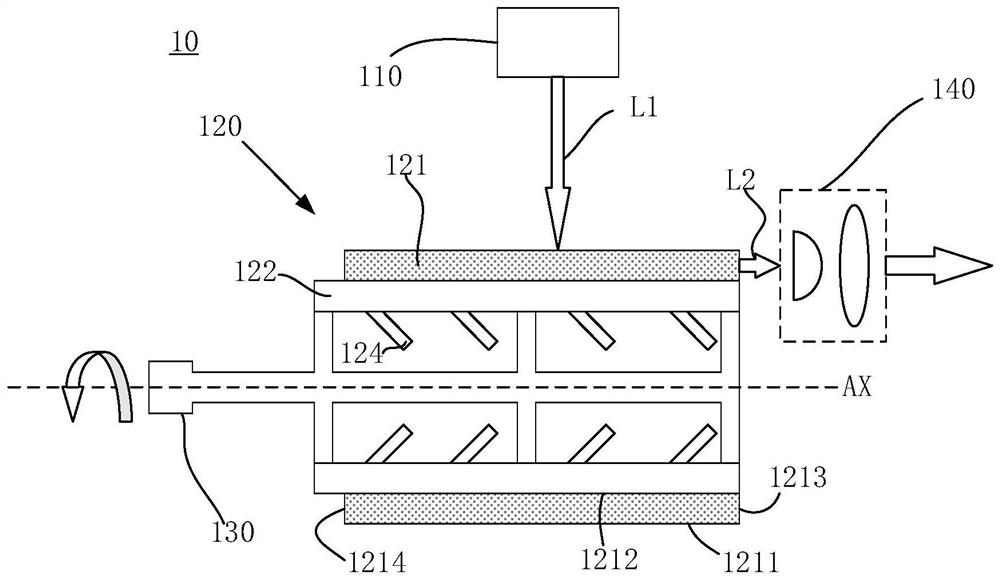
[0064] In the third embodiment, the light source device 30 includes an excitation light source 310 , a rotating drum 320 , a driving device 330 and a light collecting device 340 . For the excitation light source 310, reference may be made to the description of the excitation light source 110, 210 or 210' in the above embodiments, the driving device 330 may refer to the description of the driving device 130, and the light collection device 340 may refer to the light collection device in the above embodiments. description, which will not be repeated here.

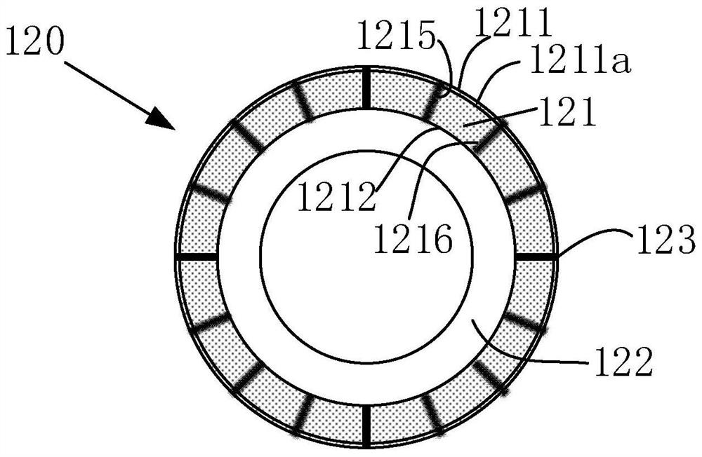
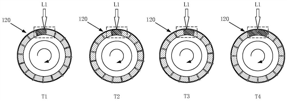
[0065] In this embodiment, the rotating drum 320 includes a cylindrical base body 322 and a plurality of wavelength conversion units 321 disposed on the side surface of the rotating drum 320 and distributed along the circumferential direction. The wavelength conversion unit 321 includes a first surface 3211 and a second surface 3212 arranged oppositely, a first end surface 3213 and a second end surface 3214 arranged oppositel...


PUM

PropertyMeasurementUnit
refractive indexaaaaaaaaaa

Abstract

The invention protects a light source device, comprising: an excitation light source, used to emit excitation light; a rotating drum, including a plurality of wavelength conversion units arranged on its side and distributed along the circumferential direction, and the wavelength conversion unit includes a wavelength conversion material for absorbing The excitation light emits the subject light, and the driving device is used to drive the rotating cylinder to rotate around its central axis; the excitation light enters the wavelength conversion unit along the radial direction of the rotating cylinder, and the subject light exits from the wavelength conversion unit along the axial direction of the rotating cylinder. By arranging the wavelength conversion unit on the peripheral side of the rotating cylinder, the excitation light is incident on the wavelength conversion unit along the radial direction of the rotating cylinder, and the received light is emitted from the wavelength conversion unit along the axial direction of the rotating cylinder, so that the incident spot of the excitation light It is completely separated from the outgoing spot of the receiving light, so that the area of ​​the incident spot can be arbitrarily enlarged without changing the size of the outgoing spot, so as to achieve high brightness and compact structure of the light source device.

Description

technical field [0001] The present invention relates to the field of optical technology, and in particular, to a light source device. Background technique [0002] Existing lighting sources are mainly LED, xenon lamp and halogen light sources. These light sources have shortcomings such as insufficient brightness, insufficient service life, and insufficient illumination distance due to large beam divergence angles. As an emerging lighting technology, laser lighting has become the development trend of future lighting due to its high brightness, long service life, and small laser beam collimation divergence angle. [0003] In order to obtain white light that can be used for illumination and display, it is necessary to use red, green, and blue lasers or to excite wavelength conversion materials (such as phosphors) by lasers. Among them, the white light obtained by the red, green and blue laser has a large color gamut range, high brightness and high cost, and is suitable for app...

Claims


Application Information

Patent Timeline
Patent Type & Authority Patents(China)
IPC IPC(8): G03B21/20G03B21/16
CPCG03B21/204G03B21/2066G03B21/2033G03B21/208G03B21/16G03B21/20G02B26/00G02F1/01
Inventor 余新张贤鹏常静李屹
Owner APPOTRONICS CORP LTD
Why Eureka
Try Eureka