
Mold for manufacturing curved part

A technology of molds and parts, applied in the field of molds for making curved parts, can solve the problems of low efficiency, failure to achieve ideal bending angle, high cost, etc., and achieve the effect of wide versatility

Pending Publication Date: 2019-10-22
HUBEI AVIATION PRECISION MASCH TECH CO LTD
View PDF0 Cites 0 Cited by
  • Summary
  • Abstract
  • Description
  • Claims
  • Application Information

AI Technical Summary

Problems solved by technology

However, due to the springback deformation of curved parts, it is often impossible to achieve the ideal bending angle in actual production. It can only be realized by correcting the angles of the punch and die through repeated trials. In stamping production, if the angle of the bent part needs to change, it cannot be adjusted in time

Method used


Image

  • Mold for manufacturing curved part
  • Mold for manufacturing curved part
  • Mold for manufacturing curved part

Examples


Embodiment Construction

[0026] In order to enable those skilled in the art to better understand the solution of the present invention, the present invention will be further described in detail below in conjunction with the accompanying drawings and specific embodiments.

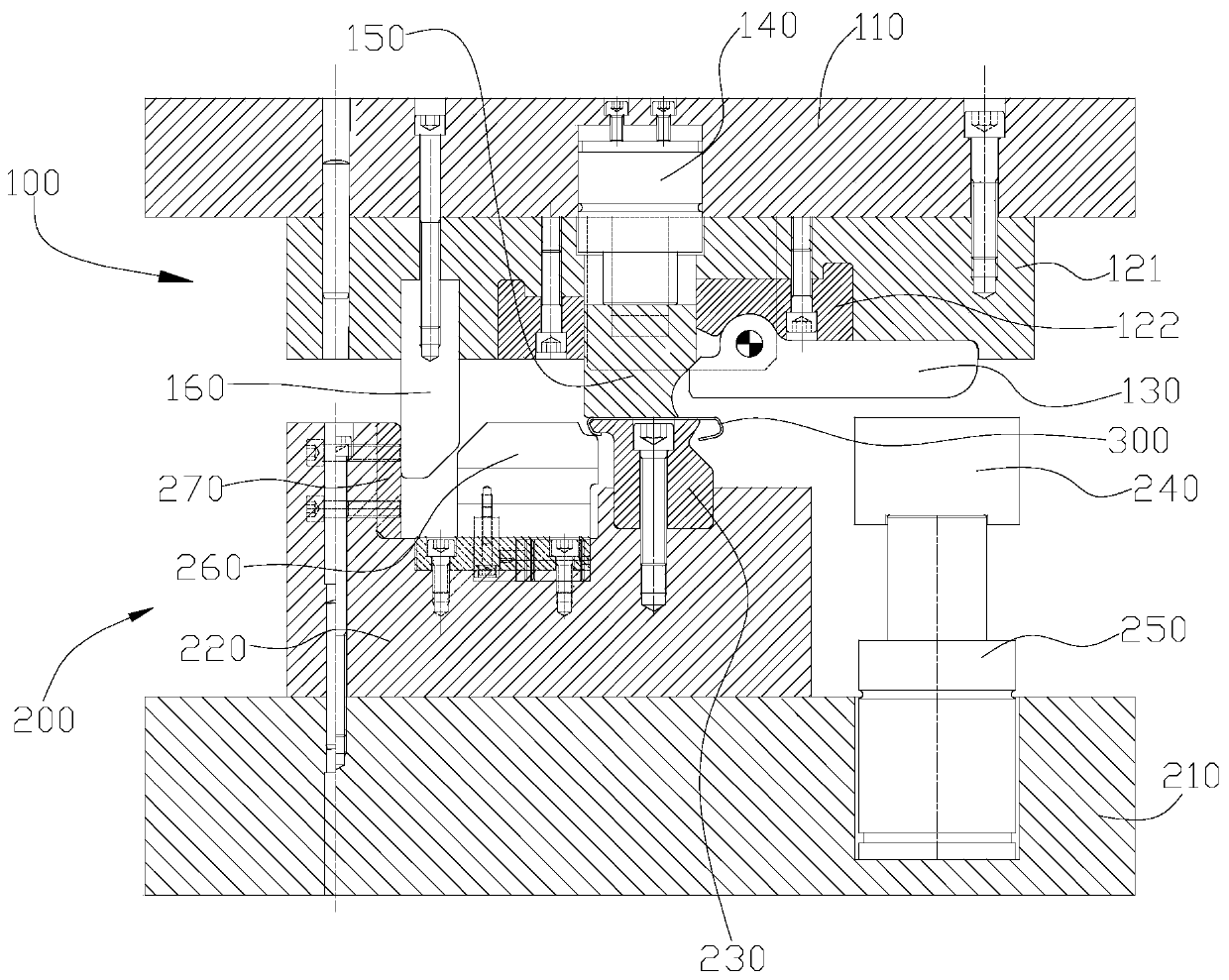
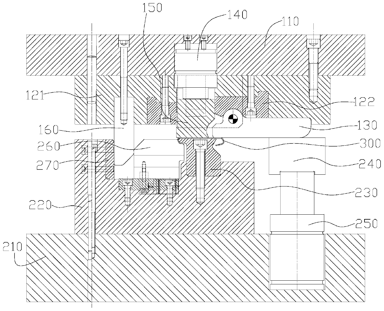
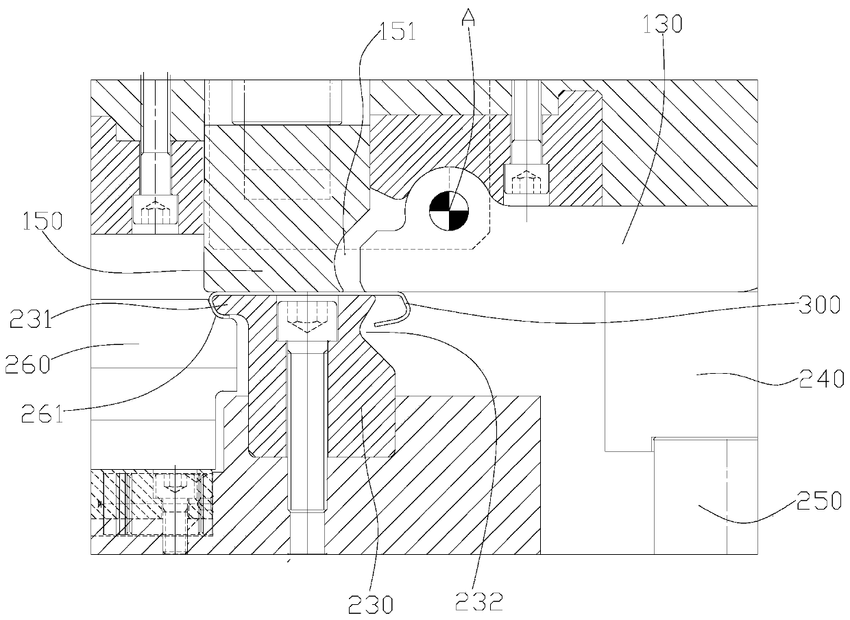
[0027] Please refer to Figure 1 to Figure 5 , figure 1 It is the structural representation of the mold before stamping in the specific embodiment; figure 2 It is a structural schematic diagram of the mold in the first stage of stamping in the specific embodiment; image 3 for figure 2 Schematic diagram of the joint between the punch and the die; Figure 4 It is a structural schematic diagram of the mold in the second stage of stamping in the specific embodiment; Figure 5 for image 3 Schematic diagram of the joint between the punch and the die.

[0028] The mold provided in this embodiment is used for making bent parts, more specifically, for making bent parts of sheet-like structures.

[0029] The mold includes an upper ...


PUM


Abstract

The invention discloses a mold for manufacturing a curved part. The mold comprises an upper mold assembly, a lower mold assembly and a driving member; the upper mold assembly comprises a concave mold,and the lower mold assembly comprises a convex mold for supporting a workpiece material sheet; the driving member can drive the upper mold assembly to move to be close to the lower mold assembly so that the first end of the concave mold can apply force to the bending position of the workpiece material sheet; the concave mold is rotatably connected to an upper mounting assembly of the upper mold assembly, and the rotation center line of the concave mold is parallel to the upper surface of the convex mold; the lower mold assembly further includes an elastic member and a heel block supported onthe elastic member and is configured to be that in the process of moving the upper mold assembly to the lower mold assembly, the second end of the concave mold can press and abut against the heel block, and the rotating center of the concave mold is located between the first end and the second end of the convex mold. The mold can compensate rebound of the curved part, the bending angle of the curved part can be adjusted without disassembling the mold or adjusting the mold during punching, the production efficiency is high, and the cost is low.

Description

technical field [0001] The invention relates to the technical field of molds, in particular to a mold for making curved parts. Background technique [0002] For parts with curved structures, it is mostly extruded by using a male die and a die with a fixed angle (adapted to the bending angle of the manufactured part). However, due to the springback deformation of curved parts, it is often impossible to achieve the ideal bending angle in actual production. It can only be realized by correcting the angles of the punch and die through repeated trials. In stamping production, if the angle of the bent part needs to change, it cannot be adjusted in time. [0003] Therefore, how to design a mold for making curved parts, which can compensate the springback of the curved parts and adjust the bending angle of the curved parts during stamping, is currently a problem that those skilled in the art need to solve technical problem. Contents of the invention [0004] The object of the p...

Claims


Application Information

Patent Timeline
IPC IPC(8): B21D5/06B21D37/10B21D43/00
CPCB21D5/002B21D5/06B21D37/10
Inventor 陈少波陈婕吴云陈凯旋
Owner HUBEI AVIATION PRECISION MASCH TECH CO LTD
Learn More