Metal punching die

A metal stamping and mold technology, applied in the field of molds, can solve the problems of processing stability or accuracy, increase the labor intensity of workers, irregular workpieces, etc., to avoid manual removal, avoid movement and warping, and reduce removal. effect of time

A metal stamping and mold technology, applied in the field of molds, can solve the problems of processing stability or accuracy, increase the labor intensity of workers, irregular workpieces, etc., to avoid manual removal, avoid movement and warping, and reduce removal. effect of time

CN110355278AActive Publication Date: 2019-10-22上海东景工艺有限公司

Image

  • Metal punching die
  • Metal punching die
  • Metal punching die

Examples


Embodiment Construction

[0024] In order to make the purpose, features and advantages of the present invention more obvious and understandable, the technical solutions in the embodiments of the present invention will be clearly and completely described below in conjunction with the accompanying drawings in the embodiments of the present invention. Obviously, the following The described embodiments are only some, not all, embodiments of the present invention. Based on the embodiments of the present invention, all other embodiments obtained by persons of ordinary skill in the art without making creative efforts belong to the protection scope of the present invention.

[0025] The technical solutions of the present invention will be further described below in conjunction with the accompanying drawings and through specific implementation methods.

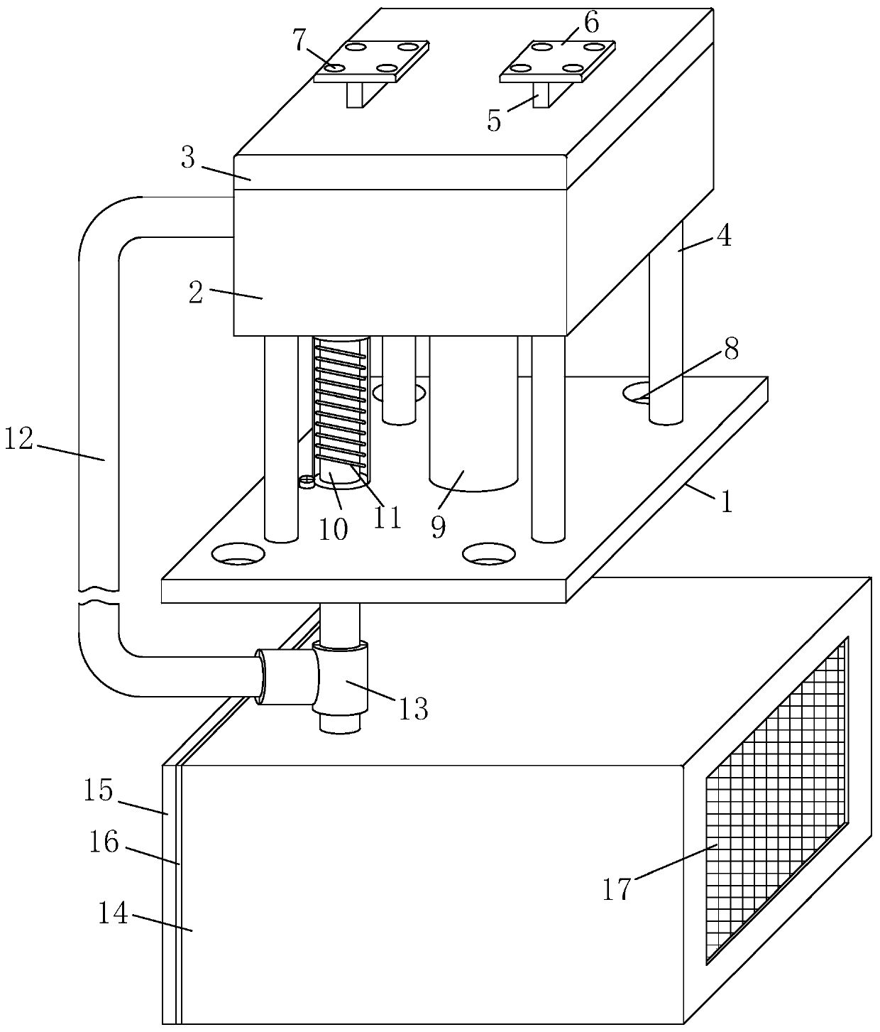
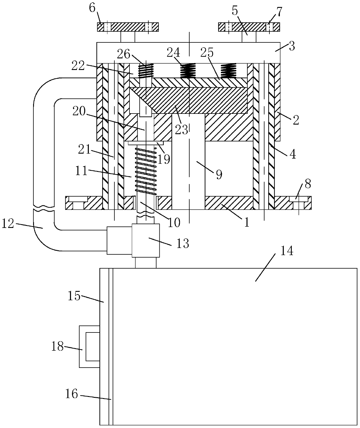
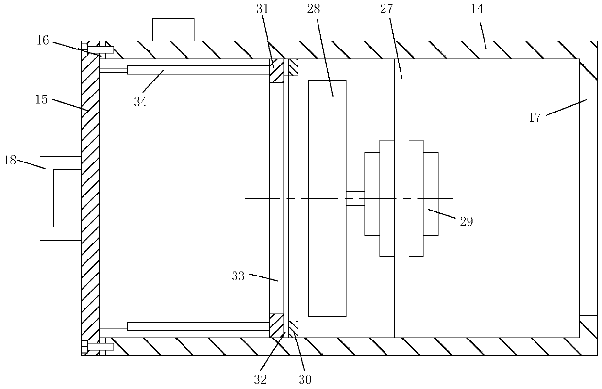
[0026] see Figure 1-6 As shown, a metal stamping die includes a lower die 2, an upper die 3, a bottom plate 1, a cleaning guide material collection structure...


PUM


Abstract

The invention belongs to the technical field of dies, and particularly relates to a metal punching die. The metal punching die comprises a bottom plate, a lower die, an upper die, guide sleeves, connecting strips, a mounting plate, a first mounting hole, second mounting holes, a fixing sleeve, an electromagnet, a guide ring, a push block, a movable iron rod, a first spring, a material guide pipe,a second spring, a connecting pipe, a three-way pipe, a dust suction box, a side plate, a first rubber ring, a first filter screen, a handle, a circular ring, a discharge hole, guide rods, a punchingcavity, metal blocks, third springs, a pressing plate, a punching rod, a mounting frame, a centrifugal impeller, a motor, a baffle ring, a frame, a second rubber ring, a second filter screen and gas springs. The metal block punching device is reasonable in structure and suitable for punching and removing excess material on one side of the metal block; and during punching, the punching rod is in contact with the metal block, and the pressing plate and the multiple third springs are arranged, so that the pressing limit of the metal block can be carried out in advance, the stability of the metalblock during punching is improved, movement and upwarping are avoided, and the punching precision is improved.

Description

technical field [0001] The invention belongs to the technical field of dies, in particular to a metal stamping die. Background technique [0002] Stamping is a pressure processing method that uses a mold installed on a press to apply pressure to the material at room temperature to cause separation or plastic deformation to obtain the required parts; during processing, part of the remaining material can be punched, or change its shape. [0003] When flushing out the remaining material of the metal workpiece, it may be necessary to use a stamping die for processing; some stamping dies carry the workpiece through the cavity, and there may be a gap between the workpiece and the cavity. When processing one side of the workpiece, and The workpiece may be irregular. When one side is under pressure, it may warp or move, which may affect the stability or accuracy of processing; after processing, manual cleaning and collection of residual materials and workpiece cleaning may be requi...

Claims


Application Information

Patent Timeline
22 Oct 2019
Publication
CN110355278A
IPC
B21D37/10; B21D43/00; B21D45/04; B08B15/04
CPC
B08B15/04; B21D37/10; B21D43/003; B21D45/04
Inventors
朱良彬; 蔡素真