Side plate connecting beam and column joint structure and connecting method

A technology of beam-column joints and side plates, which is applied to building structures and buildings, can solve problems such as poor plastic rotation capacity, difficulty in realizing the outward movement of plastic hinges on beams, strong joints and weak members, seismic requirements, and potential safety hazards.

Pending Publication Date: 2019-10-22
XI'AN UNIVERSITY OF ARCHITECTURE AND TECHNOLOGY
View PDF0 Cites 2 Cited by
  • Summary
  • Abstract
  • Description
  • Claims
  • Application Information

AI Technical Summary

Problems solved by technology

In actual engineering, the connection in the direction of the weak axis of the I-shaped column is as common as the connection of the strong axis, but the plastic rotation capacity of the widely used wedge-shaped stiffened plate connection of the weak axis of the I-shaped column is poor, and it is difficult to realize the outward movement of the plastic hinge on the beam and the " Therefore, the use of this connection form in the earthquake-resistant area has buried certain safety hazards.

Method used


Image

  • Side plate connecting beam and column joint structure and connecting method
  • Side plate connecting beam and column joint structure and connecting method
  • Side plate connecting beam and column joint structure and connecting method

Examples


Embodiment Construction

[0031] The present invention is described in further detail below in conjunction with accompanying drawing:

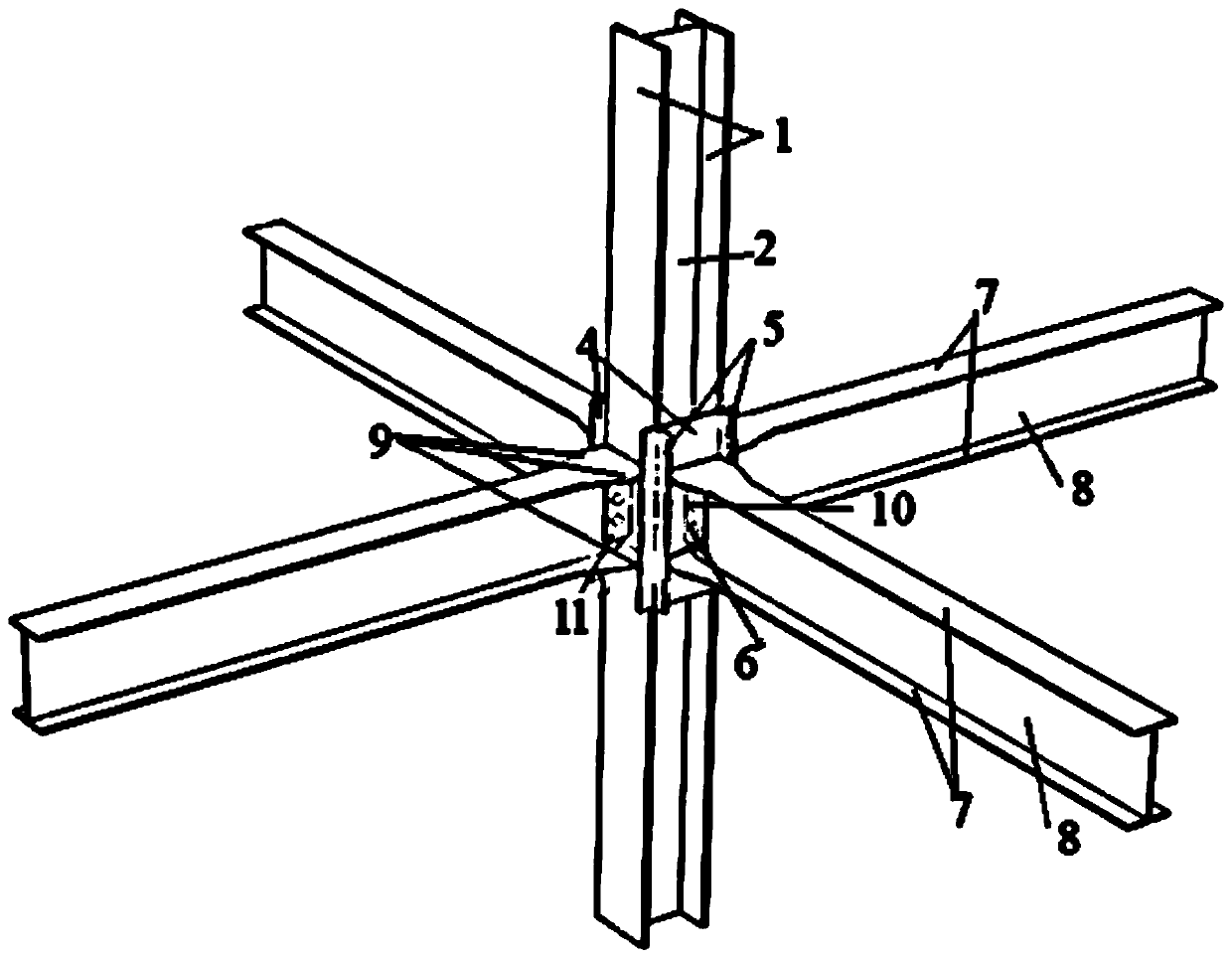
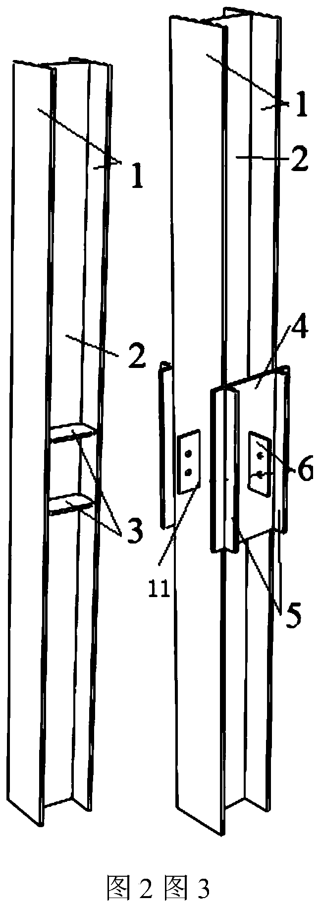
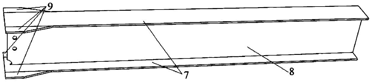
[0032] Such as Figure 1 to Figure 4 As shown, a side plate connection beam-column joint structure includes H-shaped beams, H-shaped columns, transverse stiffeners 3, side plates 4, ear plates 5, connecting plates 6 and wing expansion plates 9, and the H-shaped beam includes two Beam flanges 7 arranged in parallel, a beam web 8 is arranged between the two beam flanges 7, the plane where the largest surface of the beam web 8 is perpendicular to the plane where the largest surface of the beam flange 7 is located; the H-shaped column includes two parallel column flanges 1, A column web 2 is arranged between two column flanges 1, and the plane where the largest surface of the column flange 1 is located is perpendicular to the plane where the largest surface of the column web 2 is located; Stiffener 3, the plane where the largest face of transverse stiffener 3 is perpendic...


PUM


Abstract

The invention discloses a side plate connecting beam and column joint structure and a connecting method. Two parallelly-arranged transverse reinforcing ribs are arranged between two column flanges ofan H type column, and the planes where the maximum surfaces of the transverse reinforcing ribs are located are simultaneously perpendicular to the planes where the maximum surfaces of the column flanges are located and the plane where the maximum surface of a column web is located; side plates are welded to the H type column, and lug plates are welded to the side plates; and enlarging wing platesare arranged on the two sides of beam flanges of an H type beam in the weak axis direction of the H type column, the end faces of the beam flanges and the enlarging wing plates are welded to the otherside faces of the side plates, and the side faces of the enlarging wing plates are welded to the side faces of the lug plates. Through the arrangement of the enlarging wing plate structures, the connecting strength of a beam and column joint is improved. By the adoption of the joint structure, under the effect of cyclic loading, plastic deformation is concentrated on end beam sections reinforcedby steel beam flange enlarging wings, a joint domain is in an elastic state, outward movement of a plastic hinge on the beam can be well achieved under the effect of cyclic loading, and the requirements of the ductility and the bearing performance of the joint are increased.

Description

technical field [0001] The invention belongs to the field of construction engineering, and relates to a beam-column joint structure and a connection method for connecting side plates. Background technique [0002] The "Code for Seismic Design of Buildings" requires that "box-shaped columns should be used when columns are rigidly connected to beams in two mutually perpendicular directions." However, if box-shaped columns are used in projects where I-shaped columns can be used, the structural cost will increase. . In actual engineering, the connection in the direction of the weak axis of the I-shaped column is as common as the connection of the strong axis, but the plastic rotation capacity of the widely used wedge-shaped stiffened plate connection of the weak axis of the I-shaped column is poor, and it is difficult to realize the outward movement of the plastic hinge on the beam and the " Therefore, the use of this connection form in the earthquake-resistant area has buried ...

Claims


Application Information

Patent Timeline
Patent Type & Authority Applications(China)
IPC IPC(8): E04B1/24E04B1/58
CPCE04B1/2403
Inventor 徐莹璐
Owner XI'AN UNIVERSITY OF ARCHITECTURE AND TECHNOLOGY
Why Eureka
Try Eureka