Suspension thrust bearing unit

A technology for thrust bearings and suspensions, applied in the direction of suspensions, elastic suspensions, rolling contact bearings, etc., can solve the problems of increased damping device wear, lower cover fatigue, cracking, etc., and achieve the effect of reducing wear

Active Publication Date: 2019-10-22
AB SKF
View PDF11 Cites 0 Cited by
  • Summary
  • Abstract
  • Description
  • Claims
  • Application Information

AI Technical Summary

Problems solved by technology

This leads to the risk of premature fatigue and cracking of the lower cover, which could lead to failure of the suspension thrust bear

Method used


Image

  • Suspension thrust bearing unit
  • Suspension thrust bearing unit
  • Suspension thrust bearing unit

Examples


Embodiment Construction

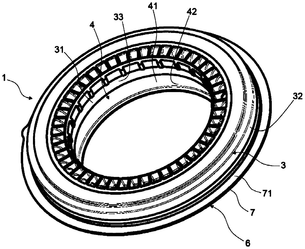
[0039] A suspension thrust bearing unit 1 having a central axis X1 is installed between a support block (not shown) connected to the chassis of the motor vehicle and a helical suspension spring (not shown) . Such a suspension thrust bearing unit 1 can be used, for example, in an automobile MacPherson strut assembly.

[0040] In the following, the adjectives “axial” and “radial” are defined with respect to the central axis X1 of the annular thrust bearing 1 .

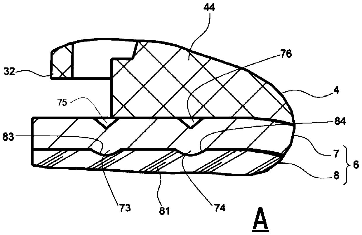
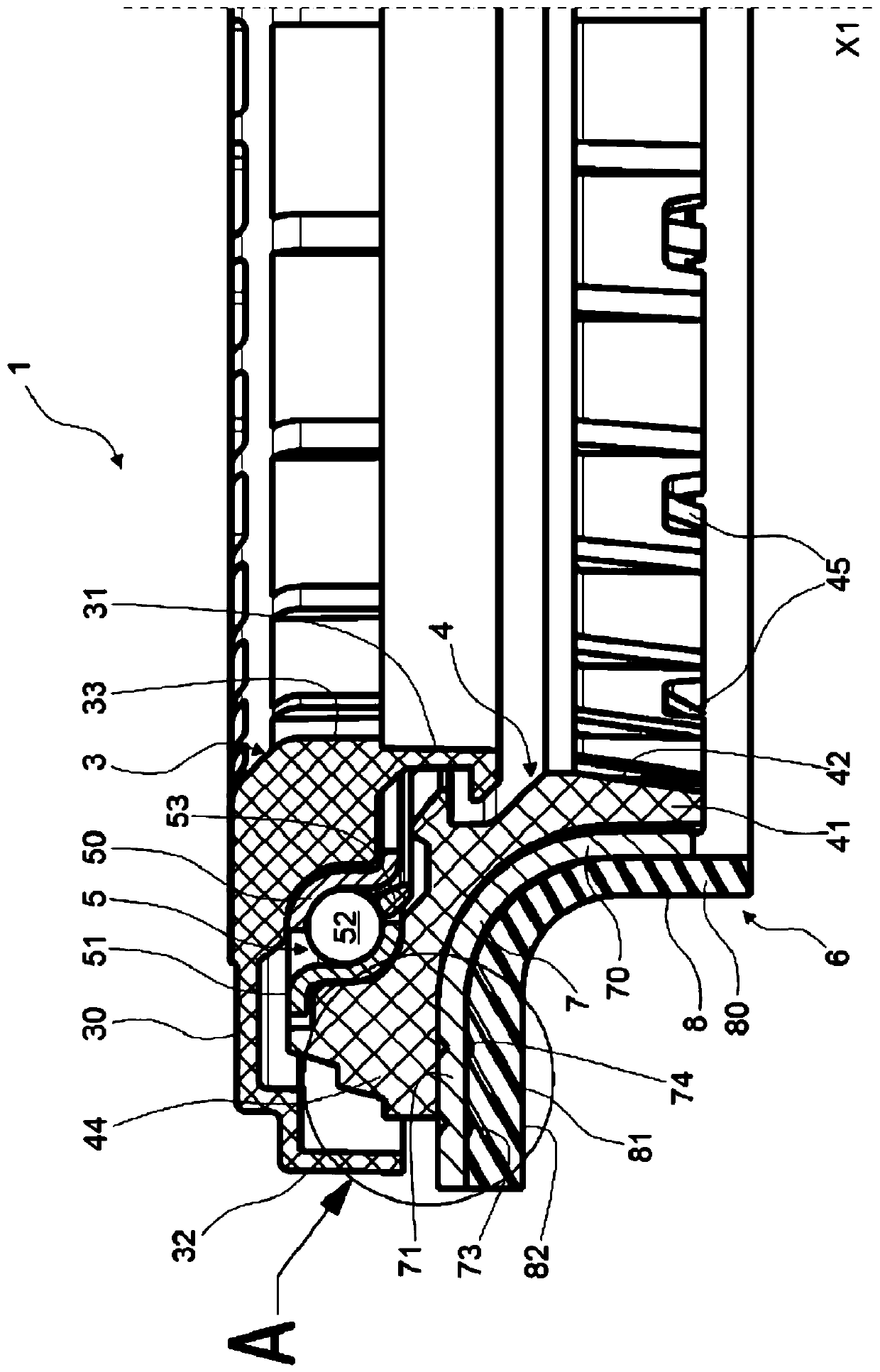
[0041] The suspension thrust bearing unit 1 includes an annular upper cover 3 , an annular lower cover 4 and a single rolling bearing 5 . These three assemblies 3, 4 and 5 have an overall circular shape around the central axis X1.

[0042] The upper cover 3 consists of a one-piece part made of a plastic composite material, for example of polyamide, optionally reinforced with glass fibres. The upper cover 3 has an upper radial portion 30 , an annular inner skirt 31 and an annular outer skirt 32 . The annular inner ski...


PUM


Abstract

The invention relates to a suspension thrust bearing unit (1) for use in an automotive suspension assembly having an upper annular cap and a lower annular cap (4) rotatable with respect to the upper annular cap (3), the upper annular cap and the lower annular cap delimiting together an annular chamber that houses a rolling bearing (5). The lower annular cap comprises a subassembly (6) for dampingvibrations and distributing stress and is provided with a lower support surface (82) that axially supports an upper end of a suspension spring. The subassembly includes an annular stiffening cup (7) made from a metal material and mounted to the lower cap, and an annular damping device (8) made from a resilient material and mounted to the stiffening cup. The stiffening cup having at least one protruding portion (73, 74) formed by stamping and that extends towards the damping device, the damping device being locally deformed by the protruding portion and forming a recess (83, 84) to receive theprotruding portion (73, 74).

Description

technical field [0001] The present invention relates to the field of suspension thrust bearing units, in particular to the field of suspension thrust bearing units of MacPherson type suspensions. Such a suspension thrust bearing unit is equipped with a suspension assembly used in a motor vehicle. Background technique [0002] In general, a motor vehicle suspension system includes a suspension assembly that supports an axle and wheels. A suspension thrust bearing unit is arranged in an upper portion of the suspension assembly, opposite the wheels and the ground, and between an upper support block attached to the vehicle body and a suspension spring. [0003] The suspension thrust bearing unit includes at least one rolling bearing. [0004] The suspension thrust bearing unit is capable of transferring axial forces between the vehicle body and the spring, while allowing relative angular motion between the spring (which moves in rotation) and a fixed support block attached to ...

Claims


Application Information

Patent Timeline
IPC IPC(8): F16C27/04B60G15/07
CPCF16C27/04B60G15/07B60G15/068B60G2204/1242B60G2204/128B60G2204/418F16C2326/05F16C27/066
Inventor 弗朗索瓦·德莱普斯朱利安·马富西布鲁诺·蒙伯夫
Owner AB SKF
Why Eureka
Try Eureka