Pin roller linear guide rail

A roller linear guide, guide rail technology, applied in the direction of linear motion bearings, shafts and bearings, bearings, etc., can solve the problems of poor integrity of the circulation system and bearing system, increased slider assembly time, processing and assembly errors, etc. The effect of shortening assembly time, increasing service life and eliminating assembly errors

Inactive Publication Date: 2019-10-22
LISHUI JIEXIANG TECH CO LTD
View PDF0 Cites 7 Cited by
  • Summary
  • Abstract
  • Description
  • Claims
  • Application Information

AI Technical Summary

Problems solved by technology

At present, the circulation system of most linear sliders is composed of multiple components, which makes the integrity of the circulation system and the bearing system poor. There is a certain error in the processing and assembly of each component, and there is a certain gap between the components. The linear slider will vibrate when it is working, the slider will not move smoothly, the service life will not be long, and too many components will increase the assembly time of the slider, which is not conducive to the improvement of production efficiency

Method used


Image

  • Pin roller linear guide rail
  • Pin roller linear guide rail
  • Pin roller linear guide rail

Examples


Embodiment Construction

[0027] The present invention will be further described below in conjunction with accompanying drawing:

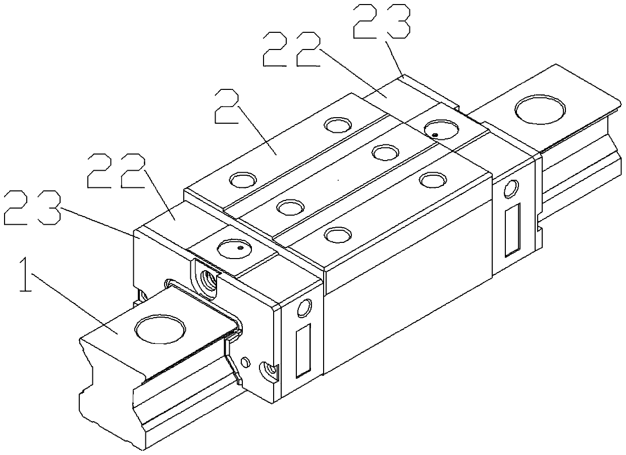
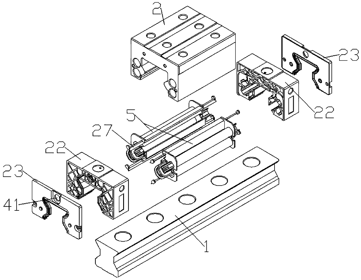
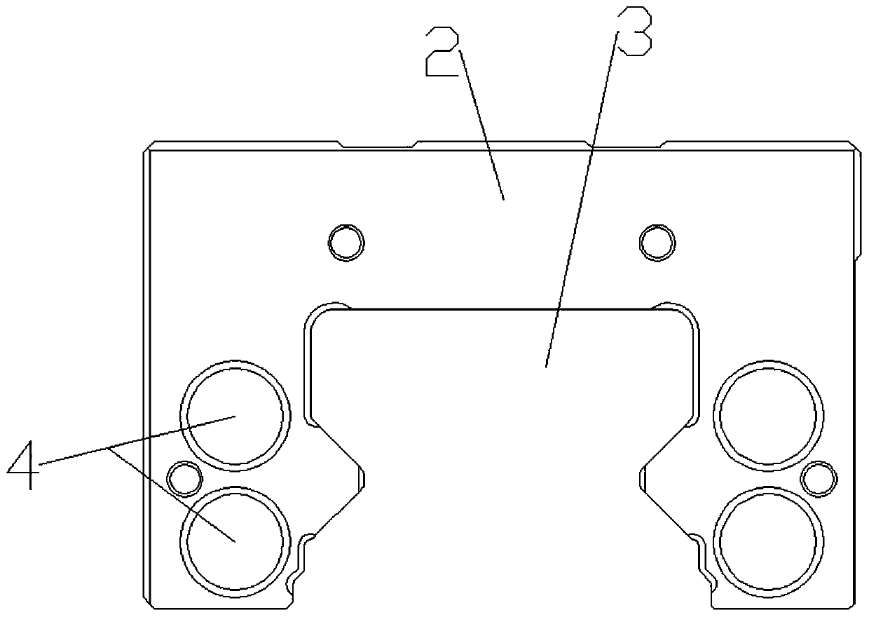
[0028] Refer to attached Figure 1-16: a kind of roller linear guide in the present embodiment, comprises guide rail 1, and described guide rail 1 upper end outer side is slidably connected with slider, and described slider comprises slider body 2, and the center position of described slider body 2 lower end is provided with installation Groove 3, the left and right sides of the installation groove 3 are respectively provided with two upper and lower circulation passages 4 opened on the inside of the slider body 2, and the left and right sides of the slider body 2 are provided with symmetrical holes about the center of the slider body 2. Circulation device 5, the circulation device 5 at the left end includes a return pipe 6 located inside the circulation channel 4, the front and rear ends of the return pipe 6 are provided with clamping plates 7 located at the front and rear...


PUM


Abstract

A pin roller linear guide rail comprises a guide rail, wherein a sliding block is arranged on the outer side of the upper end of the guide rail, the sliding block comprises a sliding block body, and amounting groove is formed in the center of the lower end of the sliding block body; two upper circulating channels and two lower circulating channels are respectively arranged on the left side and the right side of the mounting groove; circulating devices are arranged on the left side and the right side of the sliding block body; the left end circulating device comprises backflow pipes arranged on the inner side of the circulating channels; clamping plates are arranged at the front ends and the rear ends of backflow pipes; an upper support is connected to the right sides of the upper ends ofeach of the front clamping plate and rear clamping plate; a middle support is connected to the right sides of the middle ends of each of front clamping plate and rear clamping plate; a lower support is connected to the right sides of the lower ends of each of front clamping plate and rear clamping plate; the front ends of the second circulating channel and the third circulating channel are connected through a first circulating part; the front ends of the first circulating channel and the fourth circulating channel are clamped with a second circulating part; the rear ends of the first circulating channel and the fourth circulating channel are clamped with a third circulating part, the rear ends of the second circulating channel and the third circulating channel are clamped with a fourth circulating part; and the front and rear ends of the sliding block body are provided with sealing covers corresponding to the sliding block body, and the outer sides of the front sealing cover and the rear sealing cover are fixedly connected with end covers.

Description

technical field [0001] The invention relates to the technical field of linear sliders, in particular to a roller linear guide. Background technique [0002] The main operating principle of the linear slider is to use the rolling element between the slide rail and the slider to cause relative motion between the two. The linear slider is mainly composed of the following parts: bearing system, circulation system, dust-proof system and Lubrication system, the circulation system in the prior art is composed of various return components, including sealing cover, return pipe and retainer, etc., through the return component, the rolling component can be reciprocated and cyclically rolled between the slider and the slide rail; Before the block is installed on the slide rail, the (retainer) is used to support the rolling assembly to prevent the rolling assembly (balls, rollers) from falling off the slide block. At present, the circulation system of most linear sliders is composed of ...

Claims


Application Information

Patent Timeline
Patent Type & Authority Applications(China)
IPC IPC(8): F16C29/04
CPCF16C29/04
Inventor 翁海龙叶卢炼兰晓婷汤超雄
Owner LISHUI JIEXIANG TECH CO LTD
Why Eureka
Try Eureka