Automatic reversing mechanism
A technology of automatic reversing and mechanism sleeves, which is applied in the direction of engine components, valve casing structures, mechanical equipment, etc., can solve problems such as high cost, users cannot afford to buy, reversing dead point, etc., and achieve the effect of simple structure and low cost
- Summary
- Abstract
- Description
- Claims
- Application Information
AI Technical Summary
Problems solved by technology
Method used
Image

Examples
Embodiment 1
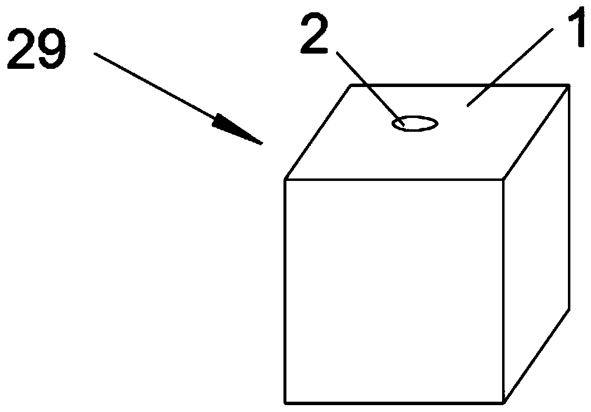
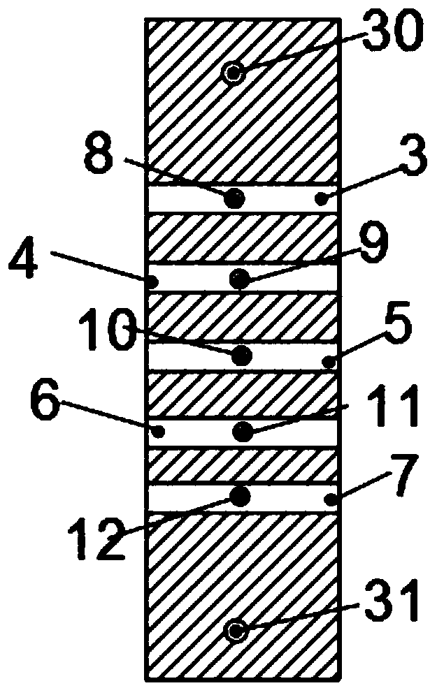
[0034] Such as Figure 1-4 , an automatic reversing mechanism 29, including a base body 1, a through hole 2 is opened on the base body 1, and an upper guide hole 30, a first groove 4, a first groove 4, and a first guide hole 30 are sequentially opened on the wall of the through hole 2 from top to bottom. Two grooves 5, the third groove 6 and the lower guide hole 31, the fluid upper outlet hole 9 is arranged on the first groove 4 groove bottom, the fluid inlet hole 10 is arranged on the second groove 5 groove bottom, the third groove The groove bottom 6 is provided with a fluid lower outlet hole 11 .
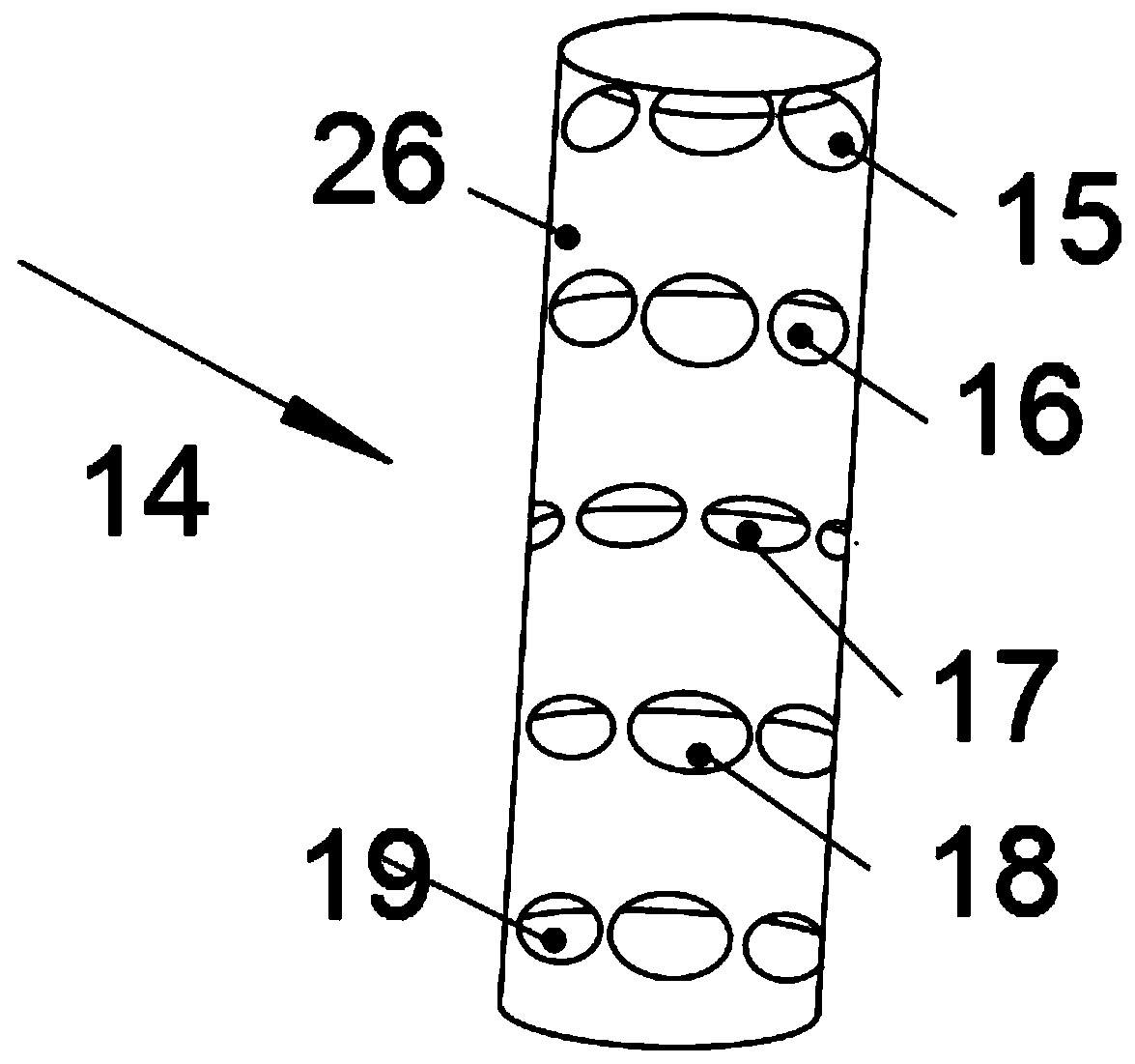
[0035] Automatic reversing mechanism 29 also comprises automatic reversing mechanism sleeve 14 and automatic reversing mechanism isolation member 13, and automatic reversing mechanism sleeve 14 comprises sleeve body 26, and sleeve body 26 is provided with first Ring hole 16, the second ring hole 17 and the third ring hole 18, the automatic reversing mechanism isolation member 13...
Embodiment 2
[0041] Such as Figure 5 , a high-pressure airless spraying machine, including a cylinder body 28, a high-pressure air intake pipe and an automatic reversing mechanism 29, the automatic reversing mechanism 29 is connected on the cylinder body 28, and the top and bottom of the automatic reversing mechanism 29 are equipped with a cover 27, automatically The reversing mechanism 29 is the automatic reversing mechanism 29 of the first embodiment.
[0042] Cylinder block 28 has piston and piston rod (in the cylinder body), upper air inlet, lower air inlet, upper valve body and lower valve body (all are the existing technology of high-pressure airless spraying machine, do not draw among the figure ).
[0043] The fluid upper outlet hole 9 is communicated with the upper air inlet, the fluid lower outlet hole 11 is communicated with the lower air inlet, the fluid inlet hole 10 is communicated with the high-pressure air intake pipe, the upper guide hole 30 is communicated with the uppe...
PUM
 Abstract
Description
Claims
Application Information
 - R&D Engineer
- R&D Manager
- IP Professional
- Industry Leading Data Capabilities
- Powerful AI technology
- Patent DNA Extraction
Browse by: Latest US Patents, China's latest patents, Technical Efficacy Thesaurus, Application Domain, Technology Topic.
© 2024 PatSnap. All rights reserved.Legal|Privacy policy|Modern Slavery Act Transparency Statement|Sitemap