Suspended face recognition system for retail store
A face recognition system and face recognition technology, which is applied in the retail field, can solve problems such as recognition errors and unclear recognition images, and achieve the effects of sufficient light, increased luminous flux, and sufficient light
- Summary
- Abstract
- Description
- Claims
- Application Information
AI Technical Summary
Problems solved by technology
Method used
Image

Examples
Embodiment
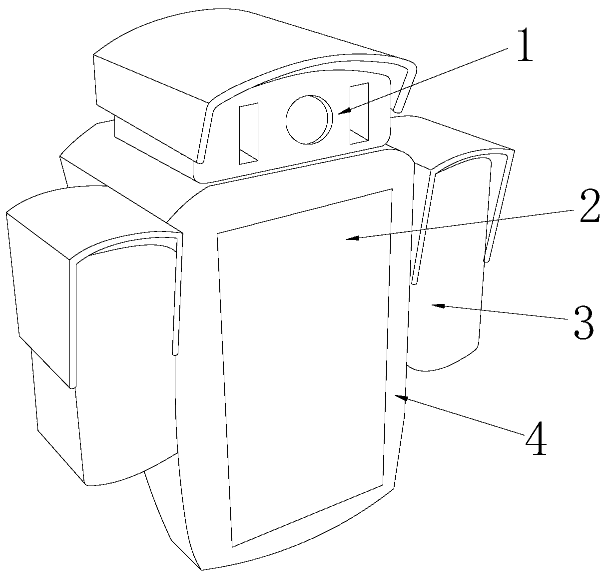
[0025] see Figure 1-Figure 6 , the present invention provides a suspended face recognition system for a retail store, the structure of which includes a face recognition machine 1, a display screen 2, a rectangular box 3, and a housing 4. The face recognition device 1 is located in the north direction of the housing 4, The housing 4 is connected with the face recognition machine 1, and the front panel of the housing 4 is provided with a display screen 2, and the display screen 2 is connected with the face recognition machine 1 through an electric signal, and the rectangular box 3 There are two, and the rectangular box 3 is arranged on both sides of the shell 4 in a symmetrical structure with respect to the shell 4;
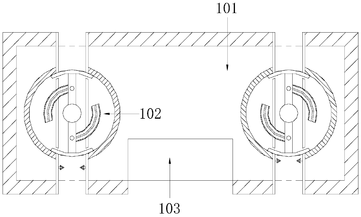
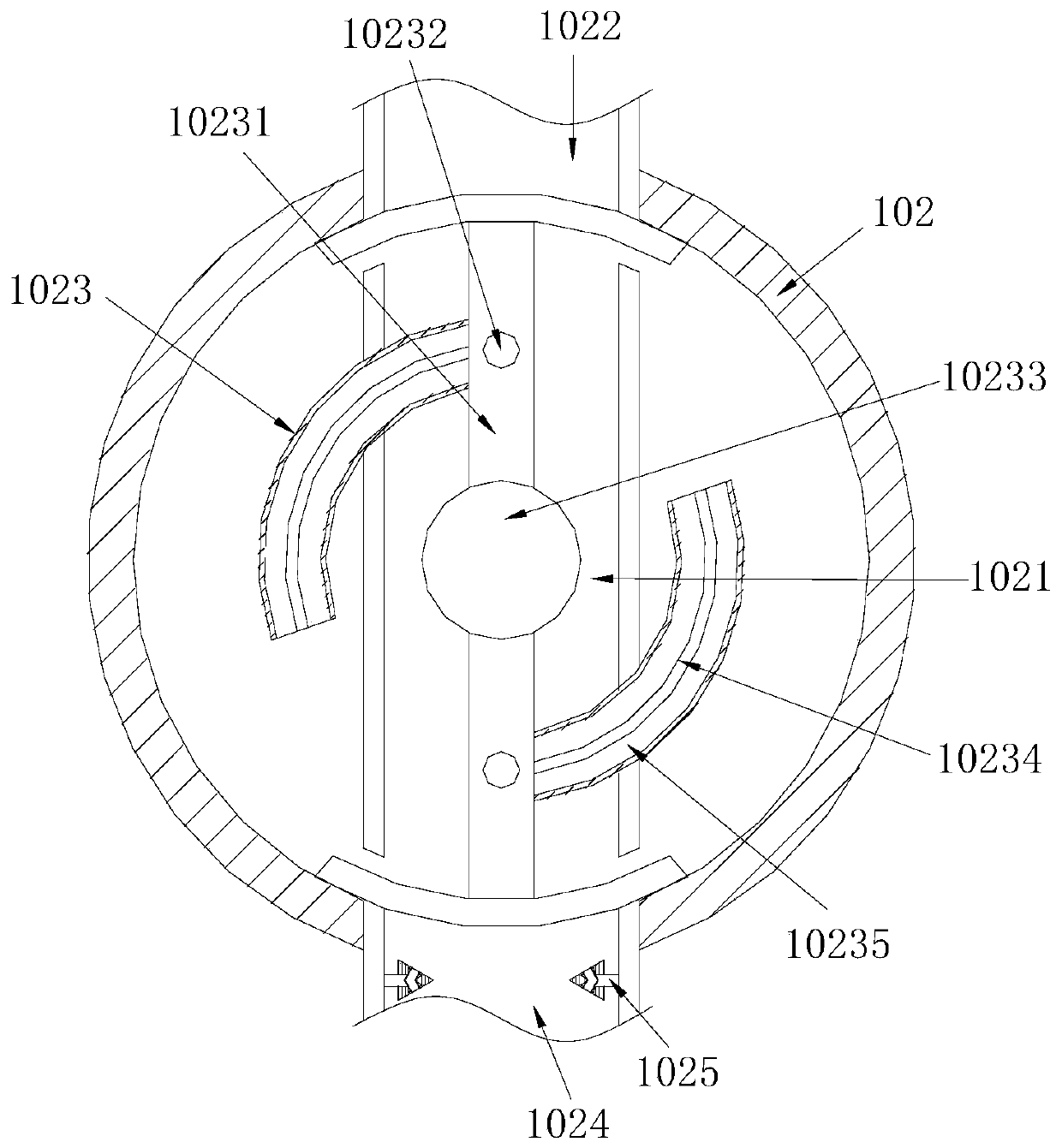
[0026] The face recognition machine 1 is composed of a working cavity 101, a light guiding device 102, and a camera 103. The light guiding device 102 and the camera 103 are installed in the working cavity 101, and the light guiding device 102 is provided with two....
PUM
 Abstract
Description
Claims
Application Information