
Terminal Equipment

A technology of terminal equipment and casing, which is applied in the field of terminal equipment and can solve problems such as poor sound effects

Active Publication Date: 2020-09-25
VIVO MOBILE COMM CO LTD
View PDF10 Cites 0 Cited by
  • Summary
  • Abstract
  • Description
  • Claims
  • Application Information

AI Technical Summary

Problems solved by technology

[0006] The invention discloses a terminal device to solve the problem that the current terminal device equipped with a receiver capable of entering and exiting the shell has a poor sounding effect

Method used


Image

  • Terminal Equipment
  • Terminal Equipment
  • Terminal Equipment

Examples


Embodiment Construction

[0031] In order to make the objectives, technical solutions and advantages of the present invention clearer, the technical solutions of the present invention will be described clearly and completely with reference to specific embodiments of the present invention and the corresponding drawings. Obviously, the described embodiments are only a part of the embodiments of the present invention, rather than all the embodiments. Based on the embodiments of the present invention, all other embodiments obtained by those of ordinary skill in the art without creative work shall fall within the protection scope of the present invention.

[0032] The technical solutions disclosed in the various embodiments of the present invention will be described in detail below with reference to the accompanying drawings.

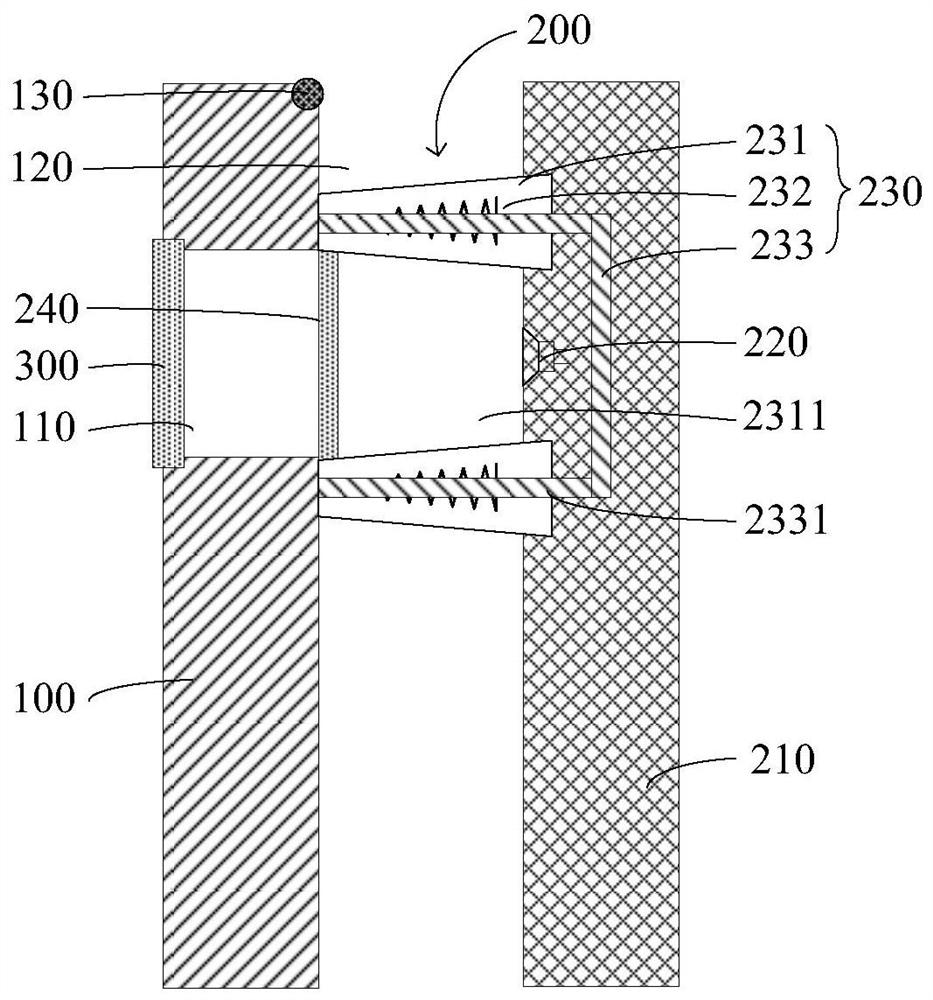
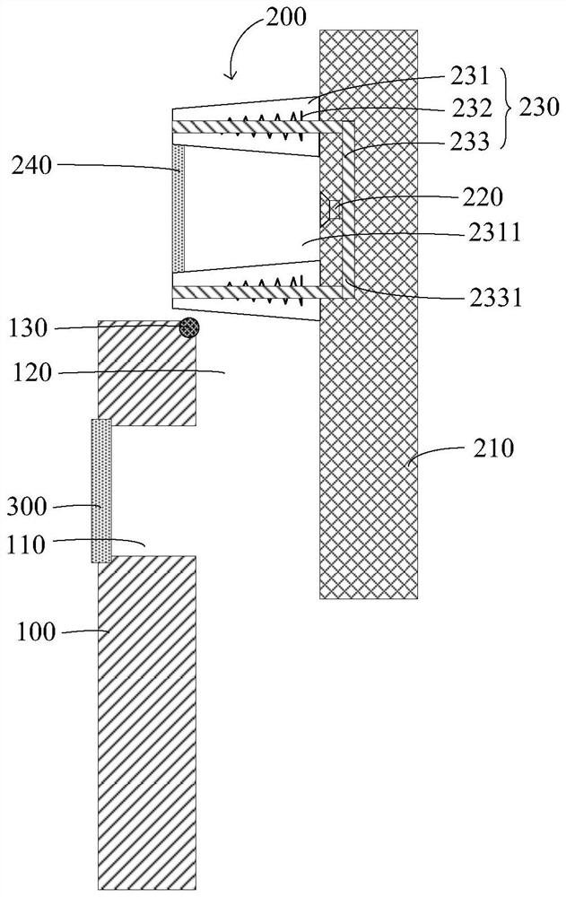
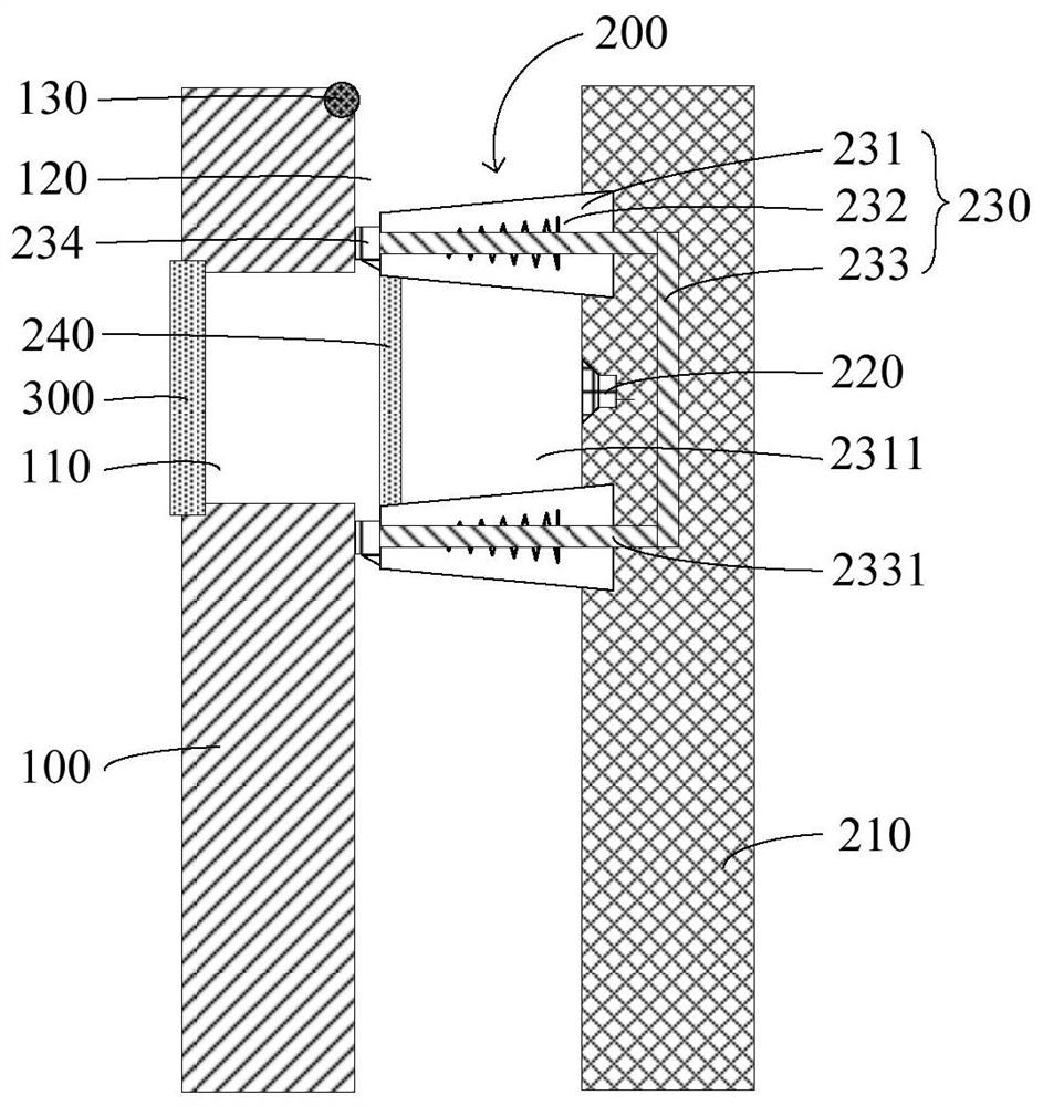
[0033] Please refer to Figure 1-Figure 4 The embodiment of the present invention discloses a terminal device. The disclosed terminal device includes a housing 100, a driven module 200, ...


PUM


Abstract

The invention discloses a terminal device. A shell has a first through-hole. A driving mechanism is connected with a driven module. The shell is provided with a first sound outlet hole. The driven module comprises a module support, a receiver and an elastic communication assembly. A rolling guide part is arranged on the side, close to the first sound outlet hole, of the outer side port of the first through hole. The elastic communication assembly comprises a second through hole and has an extension state and a contraction state, and the elastic communication assembly can be in rolling fit withthe rolling guide part along with movement of the driven module. When the driven module is located in the shell, the elastic communication assembly is in a contracted state and located between the shell and the module support, the elastic communication assembly makes contact with the shell and exerts pressure on the shell, the elastic communication assembly is in butt joint with the first sound outlet hole, and the second through hole communicates with the receiver and the first sound outlet hole. When the driven module is located outside the shell, the elastic communication assembly is in anextended state. According to the scheme, the problem of poor sound production effect of the existing terminal device can be solved.

Description

Technical field [0001] The present invention relates to the technical field of terminal device design, in particular to a terminal device. Background technique [0002] In order to increase the screen ratio of the terminal equipment, more and more terminal equipment adopts a lifting camera. When shooting is required, the camera extends out of the housing for shooting; when the shooting is completed, the camera retracts to the housing , So as to realize the hiding in the shell. The camera with this structure can avoid the occupation of the display screen layout area, so that the terminal device can be configured with a larger area display screen, and finally the screen ratio of the terminal device can be increased. [0003] The terminal device is usually equipped with a receiver. In order to improve the answering effect, the receiver is usually set in the middle of the top of the terminal device. In order to improve the self-portrait performance, the lifting camera is preferably ex...

Claims


Application Information

Patent Timeline
Patent Type & Authority Patents(China)
IPC IPC(8): H04M1/02H04M1/03
CPCH04M1/026H04M1/0264H04M1/03
Inventor 陆阿楠
Owner VIVO MOBILE COMM CO LTD
Learn More