Clamping structure for steel pipe machining
A technology for clamping structure and steel pipe, applied in workpiece clamping devices, manufacturing tools, etc., can solve problems such as steel pipe deformation, and achieve the effects of high firmness, convenient use and novel design
- Summary
- Abstract
- Description
- Claims
- Application Information
AI Technical Summary
Problems solved by technology
Method used
Image

Examples
Embodiment 1
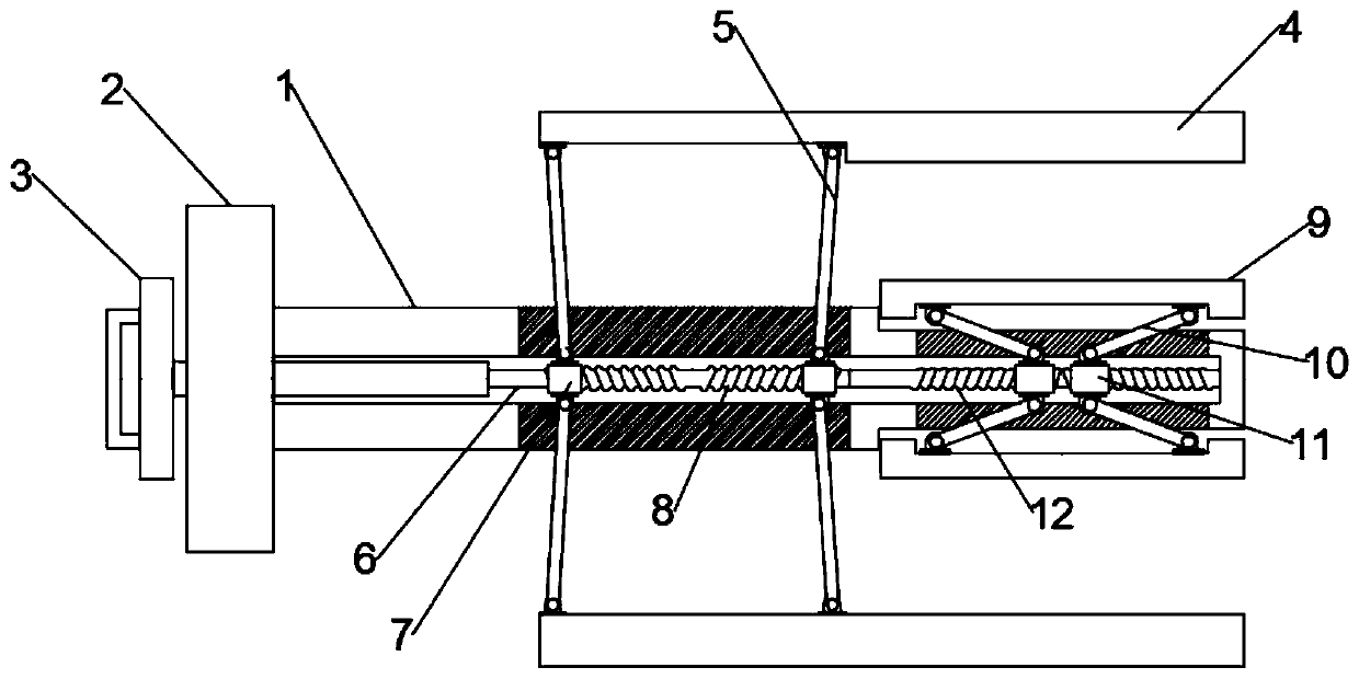
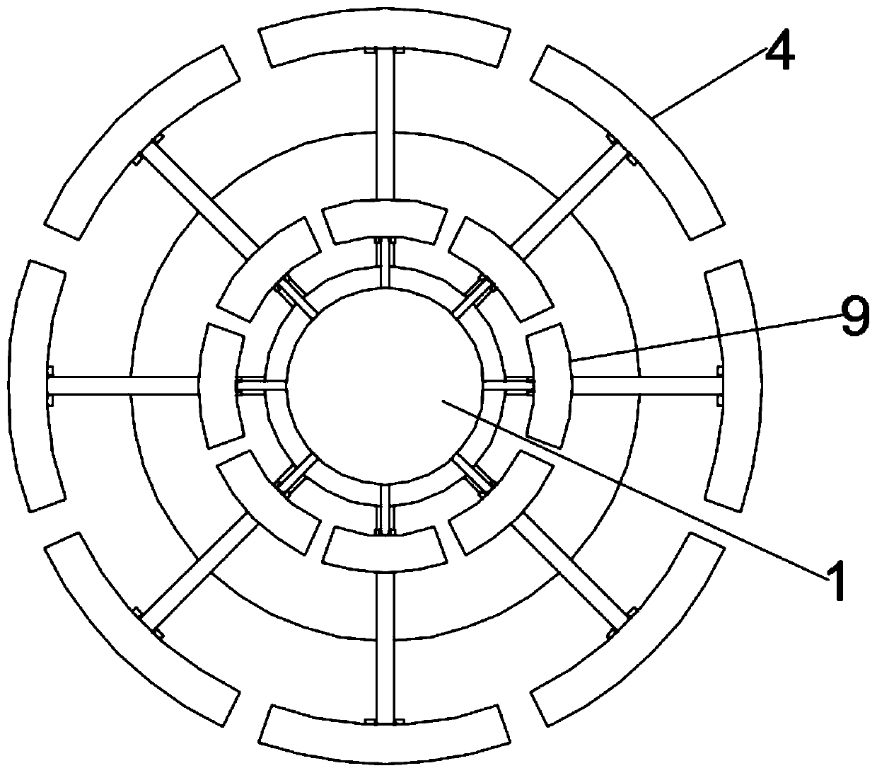
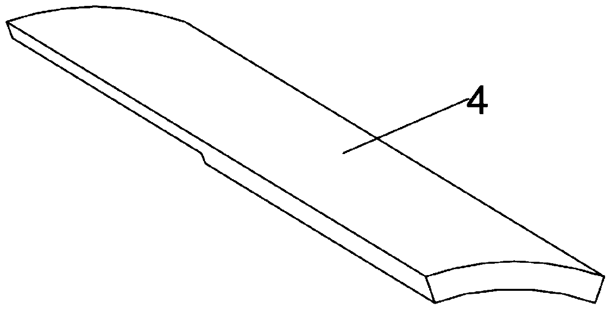
[0024] see Figure 1~3 , in an embodiment of the present invention, a clamping structure for steel pipe processing includes a support rod 1 and a mounting plate 2 fixedly connected to the support rod 1; a cavity is provided inside the support rod 1, and the inside of the cavity is from the left To the right, a rotating rod 6, a first adjustment assembly connected to the outer splint 4, and a second adjustment assembly connected to the inner support plate 9 are provided in sequence, wherein the end of the rotation rod 6 away from the first adjustment assembly passes through the mounting plate 2 and is connected with the The rotating handle 3 is fixedly connected. When the rotating rod 6 rotates, the outer splint 4 and the inner brace 9 move toward each other or move oppositely. When the outer splint 4 and the inner brace 9 move toward each other, the inner and outer walls of the steel pipe are fixed at the same time. High, and will not cause damage to the steel pipe due to one-...
Embodiment 2
[0031] see Figure 4-7 , during the specific implementation of the present invention, another embodiment is proposed to realize the separate control of the first adjustment assembly and the second adjustment assembly, specifically, the first two-way threaded rod 8 and the second two-way threaded rod 12 The two connection grooves 14 that rotate mutually are connected by rotation, and the inner side of the connection groove 14 is provided with a locking groove 16, and the locking groove 16 is engaged with the locking block 15, and the locking block 15 is connected with the connecting shaft 13 passing through the first two-way threaded rod 8 Fixedly connected, the other end of the connecting shaft 13 is fixed to the rotating rod 6. Of course, the rotating rod 6 is connected to the first two-way threaded rod 8 in rotation. When in the connecting groove 14, the rotating rod 6 drives the first two-way threaded rod 8 to rotate, and when the block 15 is in the connecting groove 14 fix...
PUM
 Abstract
Description
Claims
Application Information
 - Generate Ideas
- Intellectual Property
- Life Sciences
- Materials
- Tech Scout
- Unparalleled Data Quality
- Higher Quality Content
- 60% Fewer Hallucinations
Browse by: Latest US Patents, China's latest patents, Technical Efficacy Thesaurus, Application Domain, Technology Topic, Popular Technical Reports.
© 2025 PatSnap. All rights reserved.Legal|Privacy policy|Modern Slavery Act Transparency Statement|Sitemap|About US| Contact US: help@patsnap.com