
Implantation device and implantation method

An implanting device and implanting technology, applied in the field of implanting devices and implants, can solve the problems of great difficulty in grasping and transferring by manipulators, and affect the efficiency, accuracy and efficiency of implantation, so as to avoid improper implantation In place, improve efficiency, improve the effect of accuracy

Pending Publication Date: 2019-10-25
现代精密自动化(深圳)有限公司
View PDF10 Cites 0 Cited by
  • Summary
  • Abstract
  • Description
  • Claims
  • Application Information

AI Technical Summary

Problems solved by technology

[0002] For the implantation of small materials, the planting operation is performed manually, which is inefficient and error-prone. However, due to the small size of small materials, it is very difficult for the robot to grab and transfer the materials.
Moreover, since the implant holes on the corresponding receiving objects or devices (such as moulds, jigs, material boxes, etc.) Accuracy and efficiency are both compromised, thereby affecting the efficiency of implantation

Method used


Image

  • Implantation device and implantation method
  • Implantation device and implantation method
  • Implantation device and implantation method

Examples


Embodiment 1

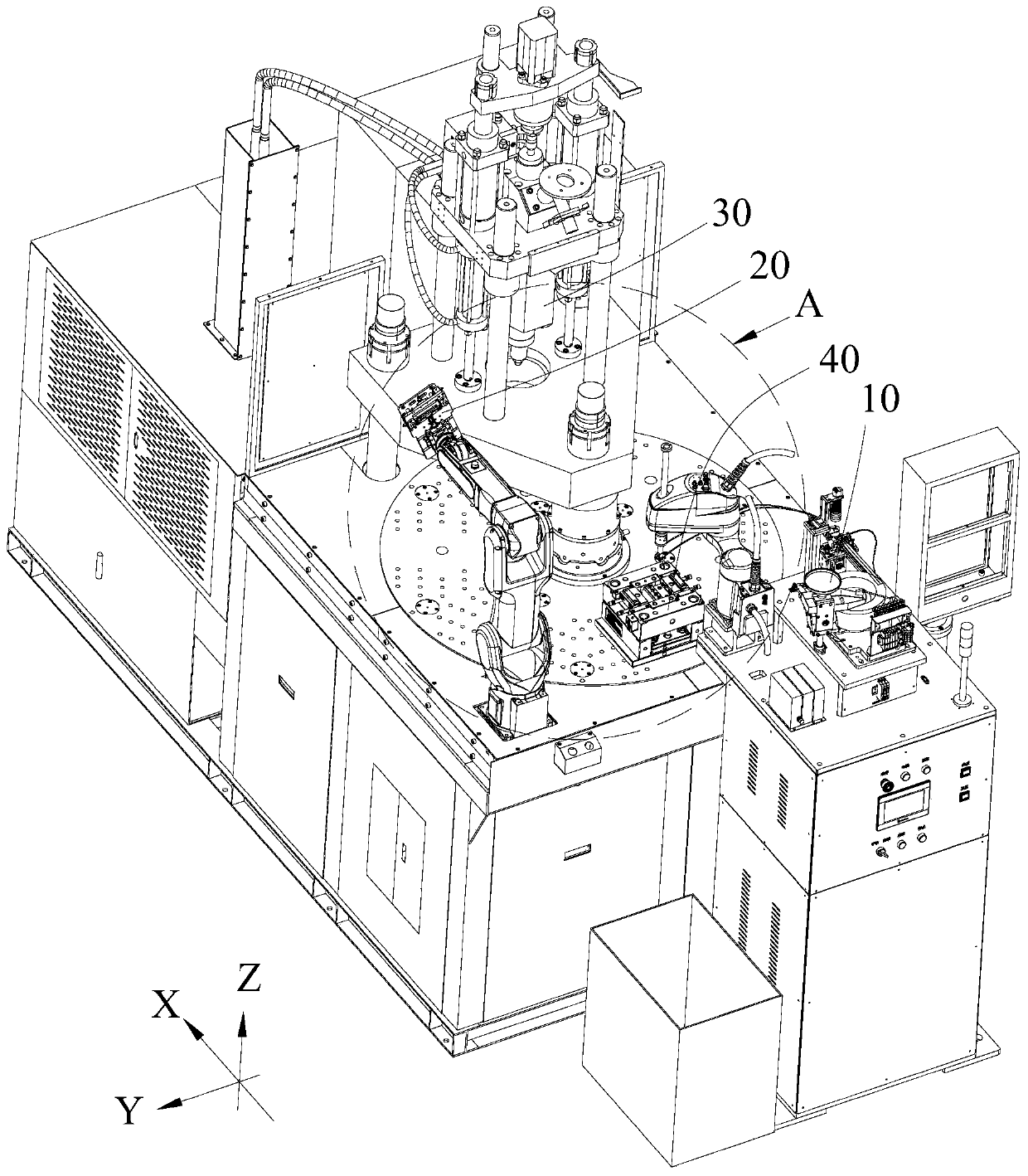
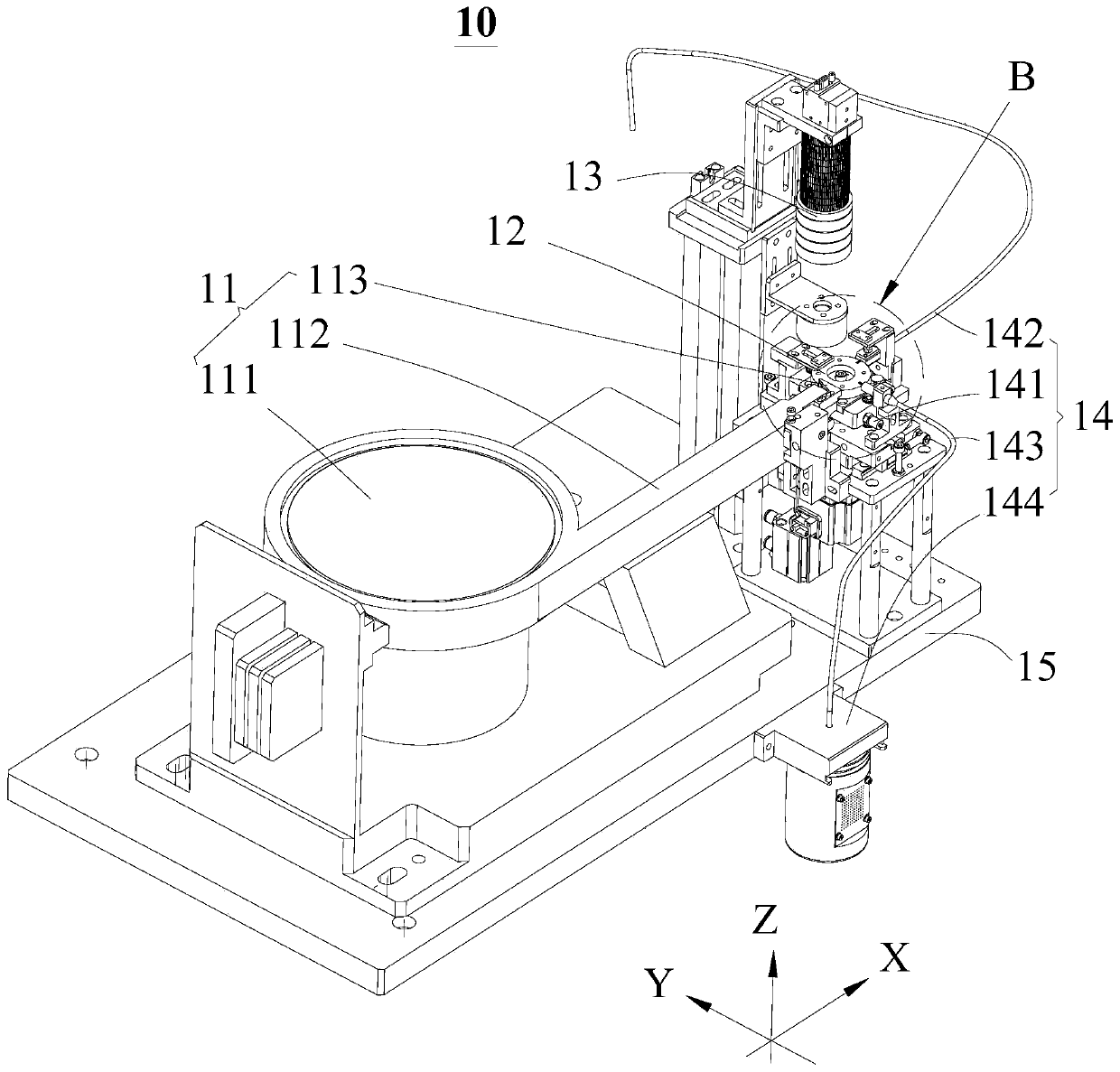
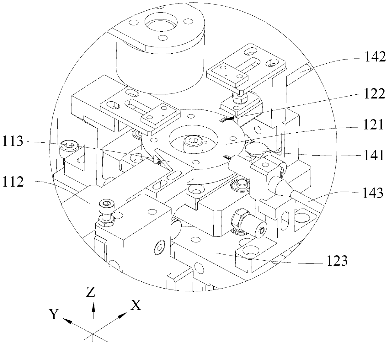
[0053] like Figure 1 to Figure 10 As shown, this embodiment provides an implanting device, which is used in conjunction with a receiving object 40 having at least one implanting hole, and is used for implanting fine materials into the implanting hole for injection molding. The fine materials have or are provided with The first characteristic part and the second characteristic part; the first characteristic part and the second characteristic part have different characteristics, and can be distinguished by the detection unit 13 described later, in the embodiment of the present invention, the fine material is a fine copper column, the first The outer diameter of the characteristic part is different from the outer diameter of the second characteristic part, wherein the first characteristic part is the small end of the fine material, and the second characteristic part is the large end of the fine material;

[0054] Of course, in other embodiments, the receiving object 40 for recei...

Embodiment 2

[0087] Please refer to Figure 11 , this embodiment provides an implantation method, which is a screening method applied to implantation equipment. For the specific structure of the implantation equipment, please refer to Embodiment 1.

[0088] The implantation method provided in this embodiment includes:

[0089] Adjustment: the vibrating plate 111 adjusts the length direction of each fine material to the front and back direction and transports them to the feeding track 112 in sequence;

[0090] Receiving: the transfer unit 12 receives fine materials from the feeding track 112 one by one and transfers them to the preset position;


PUM


Abstract

The invention is applicable to the field of implantation equipment and methods, and provides an implantation device and an implantation method. The implantation equipment comprises a screening mechanism, an implantation mechanism and an injection molding mechanism, wherein the screening mechanism is used for screening out fine materials with correct orientation in a batch of fine materials; the implantation mechanism is used for pressing the screened fine materials into an implantation hole of a receiving object; and the injection molding mechanism is used for carrying out film injection molding on the fine materials. The implantation device can ensure that the fine materials entering a discharging pipe are in the same direction, so that the subsequent production is facilitated; and meanwhile, the alignment difficulty is reduced, the precision of placement of the fine materials is improved, and the implantation efficiency is improved.

Description

technical field [0001] The invention belongs to the technical field of automatic implantation of fine materials, and in particular relates to an implantation device and an implantation method. Background technique [0002] For the implantation of fine materials, the planting operation is performed manually, which is inefficient and error-prone. However, due to the small size of the fine materials, it is very difficult for the robot to grab and transfer the materials. Moreover, since the implant holes on the corresponding receiving objects or devices (such as moulds, jigs, material boxes, etc.) Both precision and efficiency are affected, thereby affecting the efficiency of implantation. Contents of the invention [0003] The purpose of the present invention is to overcome the shortcomings of the above-mentioned prior art, and provide an implanting device and an implanting method, which aim at improving the implantation efficiency of fine materials. [0004] The present in...

Claims


Application Information

Patent Timeline
Patent Type & Authority Applications(China)
IPC IPC(8): B29C45/14B29C45/17B29C45/76B07C5/34B07C5/36
CPCB29C45/14008B29C45/76B07C5/34B07C5/36
Inventor 范开贤
Owner 现代精密自动化(深圳)有限公司
Learn More