Telescoping joint sealing structure of water turbine

A technology of sealing structure and expansion joints, which is applied in the direction of hydroelectric power generation, mechanical equipment, engine components, etc., can solve the problems of water leakage of expansion joints, changes in the compression amount of sealing strips of expansion joints, and inability to compress the sealing strips of expansion joints. The effect of water leakage problems

Active Publication Date: 2019-10-25
浙江富春江水电设备股份有限公司
View PDF4 Cites 4 Cited by
  • Summary
  • Abstract
  • Description
  • Claims
  • Application Information

AI Technical Summary

Problems solved by technology

Due to the relatively large flange surface of the draft tube, it is easy to be deformed during concrete pouring, and the sealing strip of the expansion joint may not be compacted locally, and the cantilever structure of the runner chamber will vibrate during operation, which will also cause local deformation of the sealing strip of the expansion joint. The amount of compression changes, so the expansion joint often leaks after it is installed

Method used


Image

  • Telescoping joint sealing structure of water turbine
  • Telescoping joint sealing structure of water turbine

Examples


Embodiment 1

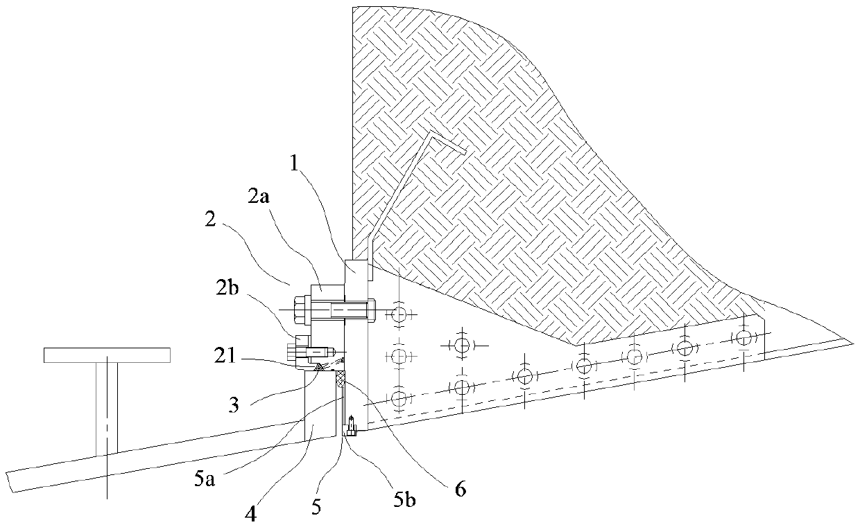
[0018] Such as figure 1 In the shown embodiment, a sealing structure of a hydraulic turbine expansion joint includes a draft tube flange 1 and a runner chamber tail flange 4, and the draft tube flange 1 and the runner chamber tail flange 4 are coaxially arranged. An expansion joint 2 is provided between the draft tube flange 1 and the tail flange 4 of the runner chamber. The expansion joint 2 includes an expansion joint pressure plate 2b and an expansion joint flange 2a. The expansion joint flange 2a and the draft tube flange 1 are fixed by bolts connect. The expansion joint pressure plate 2b is located between the expansion joint flange 2a and the rear flange 4 of the runner chamber, and the end faces of the expansion joint pressure plate 2b and the expansion joint flange 2a are fixedly connected by screws.

[0019] The inner circle of the expansion joint 2 is provided with a sealing ring 3 that is sealingly matched with the side of the flange 4 at the rear of the runner cha...

Embodiment 2

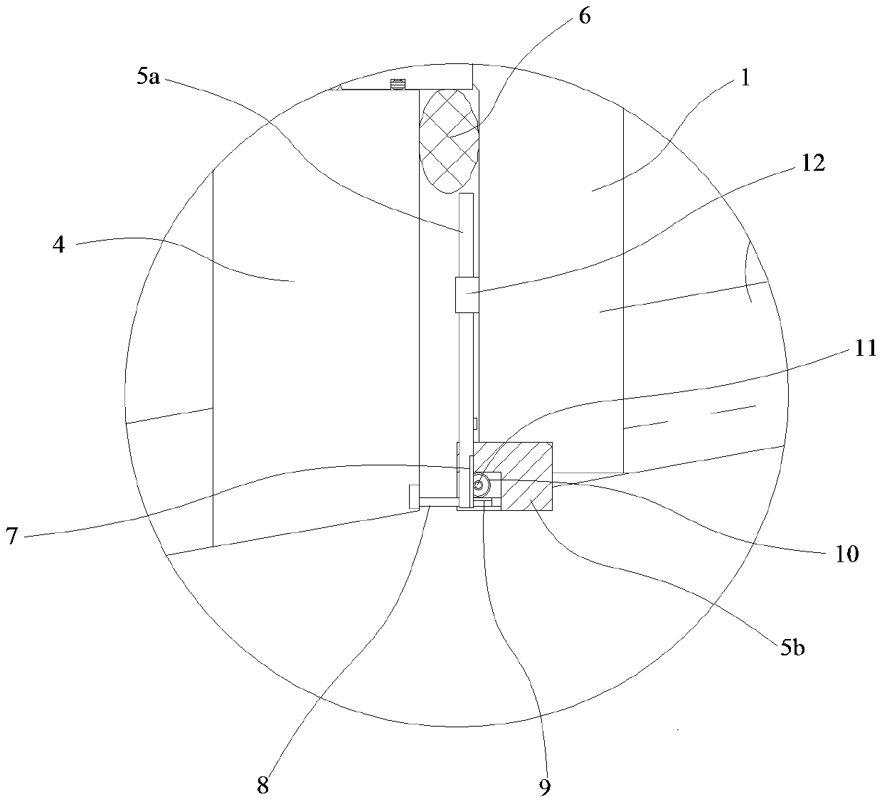
[0023] The difference between embodiment 2 and embodiment 1 is that, as figure 2 As shown, the sealing strip pressure plate 5 includes a plate body 5a and a positioning seat 5b, the plate body 5a is slidably connected with the positioning seat 5b, the positioning seat 5b is provided with a first gear 10, and the first gear 10 is provided with a coaxially fixed second gear 11. The diameter of the first gear 10 is smaller than the diameter of the second gear 11 . The plate body 5a is provided with a first rack 7 meshing with the first gear 10, the rear flange 4 of the runner chamber is provided with a rod body 8, and the rod body 8 is provided with a second rack 9 meshing with the second gear 11. 8 drives the plate body 5a to press the sealing strip 6 when it is away from the positioning seat 5b. In addition, the end surface of the draft tube flange 1 is provided with a guide block 12 slidingly fitted with the plate body 5a, and the guide block 12 guides the radial sliding of ...


PUM


Abstract

The invention discloses a telescoping joint sealing structure of a water turbine. The telescoping joint sealing structure of the water turbine comprises a tail water pipe flange and a rotating wheel chamber tail flange, wherein a telescoping joint consisting of a telescoping joint pressing plate and a telescoping joint flange is arranged between the tail water pipe flange and the rotating wheel chamber tail flange; the telescoping joint flange is fixedly connected to the tail water pipe flange; the telescoping joint pressing plate is fixedly connected to the telescoping joint flange; a sealingring which is in sealing fitting with the side surface of the rotating wheel chamber tail flange is arranged at an inner circle of the telescoping joint; a sealing strip is arranged between the end surface of the tail water pipe flange and the end surface of the rotating wheel chamber tail flange; and a sealing strip pressing plate which radially acts on the sealing strip is arranged at the innercircle of the tail water pipe flange. According to the telescoping joint sealing structure of the water turbine, the sealing effect is not influenced by the vibration of a rotating wheel chamber, andthe telescoping joint is effectively prevented from water leaking.

Description

technical field [0001] The invention belongs to the field of hydraulic turbines, and in particular relates to a sealing structure for expansion joints of hydraulic turbines. Background technique [0002] In order to compensate for the deviation caused by the installation and processing of the water guide mechanism and the runner chamber, the bulb tubular turbine is designed with an expansion joint between the runner chamber and the draft tube, so that the outer guide ring and the runner chamber have a certain degree of expansion and contraction along the axial direction. margin. Due to the relatively large flange surface of the draft tube, it is easy to be deformed during concrete pouring, and the sealing strip of the expansion joint may not be compacted locally, and the cantilever structure of the runner chamber will vibrate during operation, which will also cause local deformation of the sealing strip of the expansion joint. The amount of compression changes, so the expan...

Claims


Application Information

Patent Timeline
Patent Type & Authority Applications(China)
IPC IPC(8): F03B11/00
CPCF03B11/00F03B11/006Y02E10/20
Inventor 李俊娜周庆大张续钟凌成震沈丹杨柯龚芹炬陈璨任尚洁杨希华
Owner 浙江富春江水电设备股份有限公司
Why Eureka
Try Eureka