A pressure self-sealing leak-proof gate valve structure

A technology for preventing leakage and gate valve, applied in the field of natural gas drilling and production equipment, can solve problems such as valve function loss, wellhead valve sealing failure, and increased wellhead safety risk, and achieve the effects of quick maintenance work, prevention of internal leakage, and convenient disassembly and assembly.

Active Publication Date: 2020-11-03
SINOPEC OILFIELD EQUIP CORP
View PDF8 Cites 0 Cited by
  • Summary
  • Abstract
  • Description
  • Claims
  • Application Information

AI Technical Summary

Problems solved by technology

[0003] The purpose of the present invention is to provide a pressure self-sealing leak-proof gate valve structure, which solves the problem that the wellhead valve used in natural gas drilling is prone to sealing failure, resulting in loss of valve function and greatly increasing the safety risk of the wellhead

Method used


Image

  • A pressure self-sealing leak-proof gate valve structure
  • A pressure self-sealing leak-proof gate valve structure
  • A pressure self-sealing leak-proof gate valve structure

Examples


Embodiment Construction

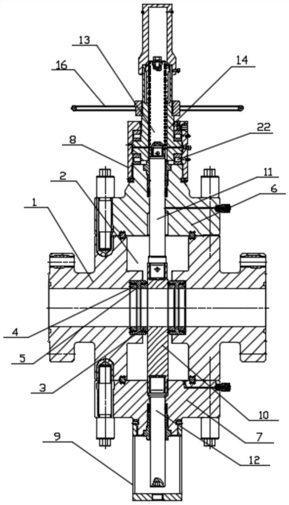
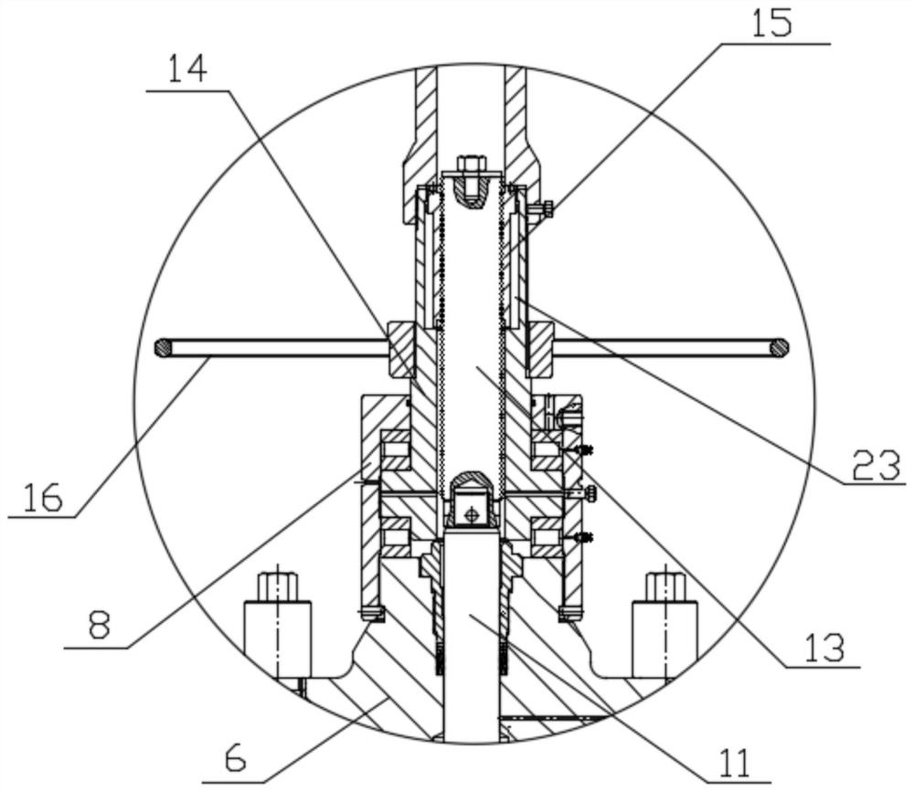
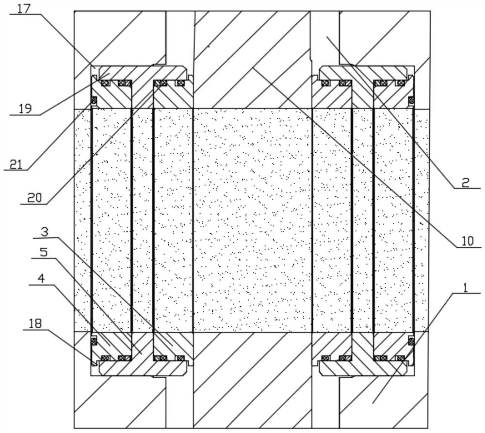
[0019] Such as Figure 1-Figure 2 As shown, a pressure self-sealing anti-leakage gate valve structure includes a valve body 1, the middle of the valve body 1 is a valve cavity 2, and the valve body 1 is sequentially provided with The rear valve seat 3 and the front valve seat 4, and a sliding sleeve 5 is arranged between the rear valve seat 3 and the front valve seat 4.

[0020] The upper and lower ends of the valve body 1 are respectively fixedly installed with an upper flange 6 and a lower flange 7, and an upper sheath 8 is fixedly installed above the upper flange 6, and the lower flange 7 A lower sheath 9 is fixedly installed below. The valve body 1 is equipped with a gate 10 in the valve cavity 2, and the upper half of the gate 10 is provided with a through hole for fluid to pass through when the valve is opened. The upper and lower ends of the gate 10 are They are respectively fixedly connected with the upper valve stem 11 and the lower valve stem 12, the upper valve st...


PUM


Abstract

The invention discloses a structure of a pressure self-sealing anti-leakage gate valve, which comprises a valve body. The middle of the valve body is a valve chamber, and the valve body is provided with rear valve seats and The front valve seat, and a sliding sleeve is arranged between the rear valve seat and the front valve seat; the upper and lower ends of the valve body are respectively fixed with an upper flange and a lower flange, and the upper flange An upper sheath is fixedly arranged above, and a lower sheath is fixedly arranged below the lower flange; the valve body is provided with a gate in the valve chamber. Both the inlet and the outlet of the valve body of the present invention adopt a double valve seat structure, and a sliding sleeve is arranged between the front and rear valve seats. Poor, realize pressure self-tightening, achieve the purpose of preventing internal leakage and ensuring sealing; and adopt balanced sliding sleeve structure, easy to disassemble and assemble, making maintenance work faster.

Description

technical field [0001] The invention relates to the technical field of natural gas drilling and production devices, in particular to a pressure self-sealing anti-leakage gate valve structure. Background technique [0002] At present, my country's shale gas development has achieved a major strategic breakthrough and has entered the stage of large-scale commercial development ahead of schedule. With the significant progress made in my country's shale gas resource evaluation, process technology system, and equipment research and development and manufacturing, it shows that my country has fully mastered the staged fracturing technology of long horizontal wells, and initially formed a series of independent cores for shale gas exploration and development. It has also made important breakthroughs in the resource evaluation system, process technology system, and fracturing equipment R&D and manufacturing. However, the core technologies of shale gas development in my country have not...

Claims


Application Information

Patent Timeline
Patent Type & Authority Patents(China)
IPC IPC(8): F16K3/02F16K3/30
CPCF16K3/0227F16K3/30
Inventor 梁长有牛晨羽杨静尉恒彪马俊伟牛永春张绍文魏自强
Owner SINOPEC OILFIELD EQUIP CORP
Why Eureka
Try Eureka