
Valve needle assembly and electronic expansion valve with valve needle assembly

An electronic expansion valve, valve needle technology, applied in the valve operation/release device, lift valve, valve details, etc., can solve the problems of reducing refrigeration efficiency, internal leakage, and failing to meet the performance requirements of electronic expansion valve, etc. Achieve the effect of reducing the driving force and balancing the force

Pending Publication Date: 2019-11-15
EMERSON CLIMATE TECH (SUZHOU) CO LTD
View PDF0 Cites 5 Cited by
  • Summary
  • Abstract
  • Description
  • Claims
  • Application Information

AI Technical Summary

Problems solved by technology

In the electronic expansion valve with the above-mentioned traditional flexible connection valve needle assembly, although it is possible to provide axial flexibility and radial flexibility by using elastic parts such as springs to effectively reduce the adverse effects caused by positional deviations caused by parts processing or assembly , however, because the electronic expansion valve does not control its axial flexibility, the electronic expansion valve is in the reverse state, especially in the reverse state of the large-diameter valve with a large flow rate due to elastic parts such as springs Due to its own flexibility and compression, the valve needle has a certain opening relative to the valve seat when the electronic expansion valve is not open, resulting in internal leakage and other phenomena, which reduces the cooling efficiency in the reverse direction
Therefore, due to the structural limitations of the valve needle assembly itself, it cannot better meet the performance requirements of the electronic expansion valve in the reverse state

Method used


Image

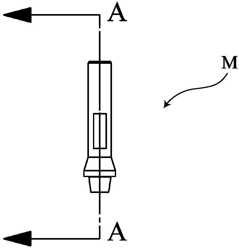
  • Valve needle assembly and electronic expansion valve with valve needle assembly
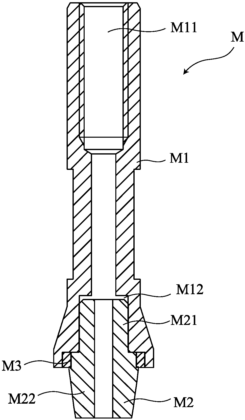
  • Valve needle assembly and electronic expansion valve with valve needle assembly
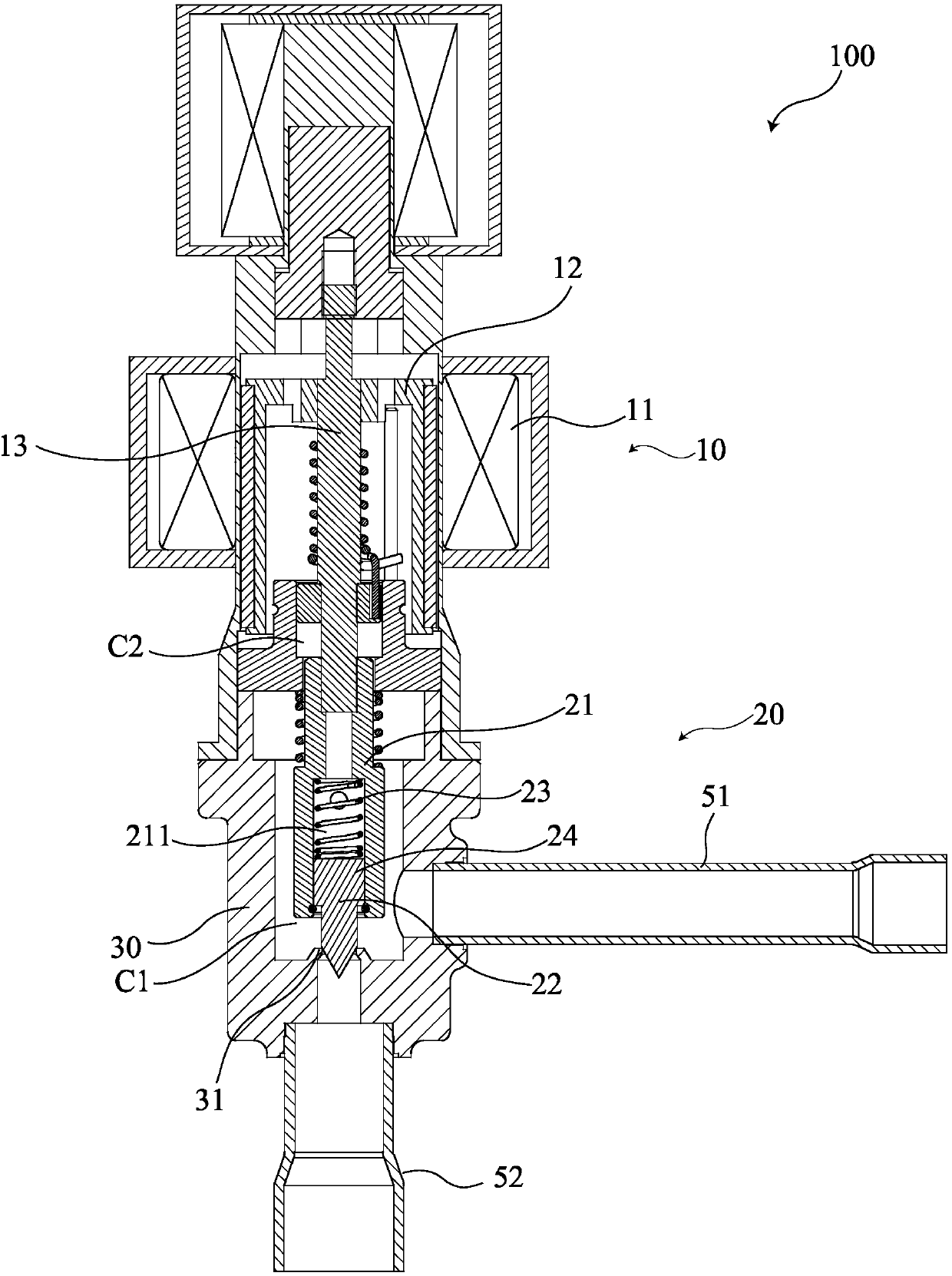
  • Valve needle assembly and electronic expansion valve with valve needle assembly

Examples


Embodiment Construction

[0040] The following description is merely exemplary in nature and is not intended to limit the invention, application and uses. It should be understood that throughout the several drawings, like reference numerals indicate the same or similar parts and features. The various drawings only schematically represent the concept and principle of the embodiments of the present invention, and do not necessarily show the specific dimensions and proportions of the various embodiments of the present invention, which may be used in specific drawings or specific parts of the drawings. Relevant details or structures of various embodiments of the present invention are illustrated in an exaggerated manner.

[0041] In the description of the embodiments of the present invention, the orientation terms related to "upper" and "lower" are used to describe the upper and lower positions of the views shown in the drawings, and the "positive direction" used ", "Reverse" is defined according to the f...


PUM


Abstract

The invention relates to a valve needle assembly and an electronic expansion valve with the valve needle assembly. In one aspect, the invention provides the valve needle assembly. The valve needle assembly comprises a valve rod, a valve needle, an elastic element and a stop structure; the valve needle is connected to the valve rod and can move in the axial direction relative to the valve rod; theelastic element is arranged between the valve rod and the valve needle; and the stop structure is configured to limit the axial movement of the valve needle relative to the valve rod so as to preventthe valve needle from opening a valve port of the electronic expansion valve in advance under the acting force of fluid. In another aspect, the invention provides the electronic expansion valve. The electronic expansion valve comprises the valve needle assembly. According to the valve needle assembly and the electronic expansion valve, the phenomenon that internal leakage is caused due to the factthat the electronic expansion valve is opened in advance under the action of the fluid can be avoided, and the flow of the fluid flowing through the electronic expansion valve can be accurately controlled in a forward state and a reverse state; and in addition, the electronic expansion valve is provided with a balance passage, so that the stress of the valve needle assembly can be effectively balanced.

Description

technical field [0001] The invention relates to a valve needle assembly and an electronic expansion valve with the valve needle assembly. Background technique [0002] The statements in this section merely provide background information related to the present disclosure and may not constitute prior art. [0003] The electronic expansion valve is an important part in the refrigeration system, which is used to regulate the flow of the working fluid. An electronic expansion valve usually includes a drive mechanism, a throttling mechanism and related auxiliary mechanisms. The driving mechanism usually includes a stepping motor and a corresponding threaded screw mechanism, and the throttling mechanism includes a valve needle assembly and a valve seat. In a traditional electronic expansion valve, usually a stepping motor and a threaded screw mechanism directly drive the valve needle assembly to open or close the electronic expansion valve, thereby realizing the adjustment of the...

Claims


Application Information

Patent Timeline
IPC IPC(8): F16K1/32F16K1/38F16K1/50F16K27/02F16K31/04F16K39/02
CPCF16K1/32F16K1/385F16K1/50F16K27/0254F16K31/047F16K39/02
Inventor 陈亮
Owner EMERSON CLIMATE TECH (SUZHOU) CO LTD
Learn More