Liquid crystal display panel and display device comprising same

A liquid crystal display panel and display area technology, applied in optics, instruments, nonlinear optics, etc., can solve the problems of electrochemical corrosion, large electrochemical corrosion, etc., to increase the protection effect, ensure normal conversion, and reduce the relative area. Effect

Inactive Publication Date: 2019-10-25
TCL CHINA STAR OPTOELECTRONICS TECH CO LTD
View PDF3 Cites 8 Cited by
  • Summary
  • Abstract
  • Description
  • Claims
  • Application Information

AI Technical Summary

Problems solved by technology

However, due to the variety of GOA signals, the lines in the GOA area need to be changed frequently through via holes, so there is a risk of electrochemical corrosion. Greater risk of chemical corrosion

Method used


Image

  • Liquid crystal display panel and display device comprising same

Examples


Embodiment 1

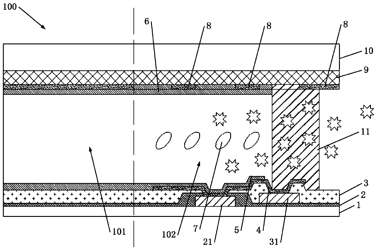
[0035] Such as figure 1 As shown, a liquid crystal display panel 100 includes a display area 101 and a non-display area 102 surrounding the display area 101 . The liquid crystal display panel 100 in the non-display area 102 includes an array substrate, a color filter substrate, a liquid crystal layer 7 and a sealant layer 11, wherein the color filter substrate is arranged opposite to the array substrate, and the liquid crystal layer 7 is arranged on Between the array substrate and the color filter substrate, the sealant layer 11 is disposed around the liquid crystal layer 7 .

[0036] Such as figure 1 As shown, the array substrate includes: a first substrate 1 , a gate insulating layer 2 , a passivation layer 3 , a first electrode layer 4 , and a first polyimide layer 5 .

[0037] Such as figure 1 As shown, the gate insulating layer 2 is disposed on the first substrate 1 , and the gate insulating layer 2 is provided with a first metal layer 21 . The gate insulating layer 2...


PUM


Abstract

The invention relates to a liquid crystal display panel and a display device comprising the same. The liquid crystal display panel comprises a non-display region, wherein a second electrode layer of the non-display region is configured to be a plurality of electrode line segments at intervals, so as to remove single-side electrodes forming an electrolytic tank, and reduce the relative area of thesecond electrode layer and a first electrode layer, thereby avoiding electrochemical corrosion in via holes of a fan-out region caused by the formation of the electrolytic tank, and improving the reliability of products. Further, since the gaps between the electrode line segments of the second electrode layer are filled with a material adopted by a second polyimide layer, the thickness of the second polyimide layer at the gap positions is increased, the protective effect on the second electrode layer is improved, the normal conversion of signals is ensured, and the reliability of the productsis enhanced.

Description

technical field [0001] The invention relates to the field of display technology, in particular to a liquid crystal display panel and a display device thereof. Background technique [0002] The display device can convert the data of the computer into various characters, numbers, symbols or intuitive images and display them, and can use keyboard and other input tools to input commands or data into the computer, and add, delete, modify and change the display at any time with the help of the system's hardware and software. content. Display devices are classified into plasma, liquid crystal, light emitting diode, and cathode ray tube according to the display device used. [0003] The working principle of CRT (abbreviation for Cathode Ray Tube) cathode ray tube display is that the filament heats up after being energized, the cathode is excited, and the electron flow is emitted. The electron flow is accelerated by the internal metal layer with high voltage, and is formed by lens f...

Claims


Application Information

Patent Timeline
Patent Type & Authority Applications(China)
IPC IPC(8): G02F1/1343G02F1/1337
CPCG02F1/133723G02F1/134309G02F1/134327G02F1/1339G02F1/13454G02F1/136286G02F1/133512G02F1/133514G02F1/134318
Inventor 胡建忠谢克成张扬刘军正
Owner TCL CHINA STAR OPTOELECTRONICS TECH CO LTD
Why Eureka
Try Eureka