Tire zero point positioning method

A zero-point positioning and tire technology, which is applied in automobile tire testing, computer components, electromagnetic radiation induction, etc., can solve problems such as complex control, high system cost, and small detection range of color difference sensors, and achieves a large scanning field of view and simple control methods , The effect of simplifying the hardware structure and operation mode

Active Publication Date: 2019-10-25
BEIJING LANGSHENGFENG MEASUREMENT & CONTROL TECH CO LTD
View PDF6 Cites 1 Cited by
  • Summary
  • Abstract
  • Description
  • Claims
  • Application Information

AI Technical Summary

Problems solved by technology

[0006] Although the above technical solution realizes the zero point positioning of the tire barcode, due to the small detection range of the color difference sensor, it is necessary to properly adjust the position of the color difference sensor. Can’t read the barcode information, if you want to bind the barcode, you need at least two sets of sensors, and two sets of fixed-point actuators in the horizontal and vertical directions to locate the barcode position, resulting in high overall system cost and complicated control

Method used


Image

  • Tire zero point positioning method
  • Tire zero point positioning method
  • Tire zero point positioning method

Examples


Embodiment Construction

[0040] The present invention will be described in further detail below in conjunction with the accompanying drawings.

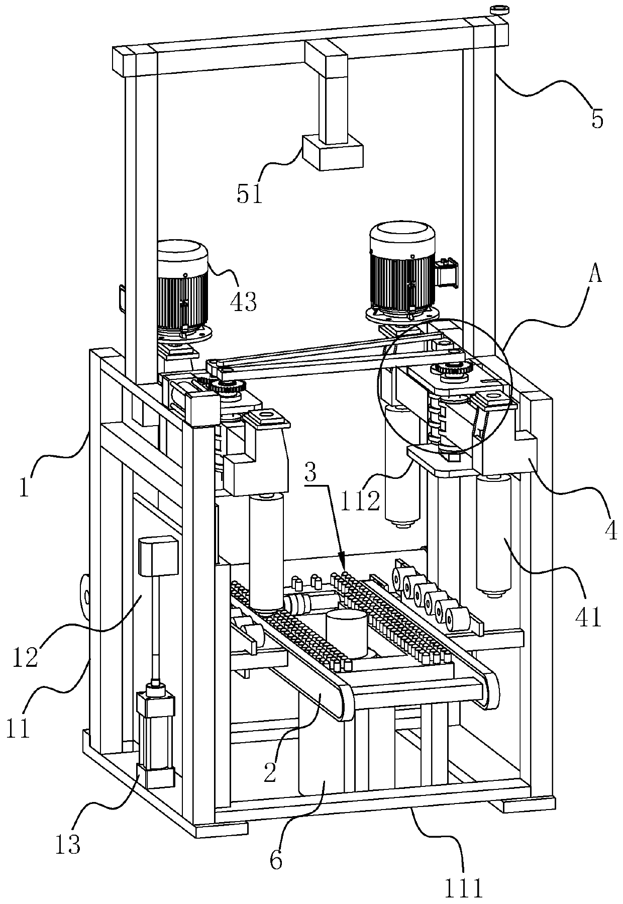
[0041] refer to figure 1 , is a tire zero point positioning device disclosed in this embodiment, including a main body frame 1, two conveyor belts 2 located between the main frame 1, a lifting drive device for driving the conveyor belt 2 to move vertically, and a lifting drive device located between the two conveyor belts 2 The inner rotary table 3, the lifting brake device 6 located at the center of the rotary table 3, the positioning sensor 51 located above the conveyor belt 2, and the controller cooperating with the positioning sensor 51, two arms are arranged on the outer sides of the two conveyor belts 2 respectively. 4. After the tire is placed on the conveyor belt 2, the tire is moved directly above the lifting brake device 6 through the conveyor belt 2, and the tire position is fixed by the lifting brake device 6 and four arms 4, and the position of ...


PUM


Abstract

The invention provides a tire zero point positioning method. A testing machine comprises a main body frame, two conveying belts located between the main body frame and a centering rotating mechanism for driving a tire to rotate at a fixed point. The positioning method comprises the steps of 1, positioning a tire through the centering rotating mechanism; 2, scanning the tire through a bar code scanner; 3, carrying out image filtering treatment; 4, positioning the straight line information through hough transformation; 5, acquiring the central position of the bar code; 6, calculating the offsetof the center position of the bar code relative to the center line positions of the two conveying belts; and 7, controlling the tire to rotate according to the offset. Due to the fact that the scanning visual field of the bar code scanner is large, one bar code scanner can achieve reading of the tire bar code and bar code zero point positioning. The control mode is simple and convenient. The tirespecification is replaced without adjusting the position. The extra hardware cost is not needed, and the zero point positioning cost is reduced.

Description

technical field [0001] The invention relates to the technical field of tire factory inspection, in particular to a tire zero point positioning method. Background technique [0002] Strict quality inspection of tires is an important production link to ensure the quality of tires and ensure the safety of vehicles. [0003] Tires often have uneven size, rigidity, and unbalanced quality. The detection of this unevenness is achieved through tire uniformity and dynamic balance tests. Tire radial force fluctuations and lateral force fluctuations due to non-uniformity will affect the ride comfort, handling stability and safety of the vehicle. The faster the car travels, the more obvious this effect is, so tire companies regard the uniformity test and dynamic balance test of car tires as one of the key indicators for tire quality control. [0004] During the tire testing process, the test data of one week of tires is mostly uploaded to the computer through the force-measuring senso...

Claims


Application Information

Patent Timeline
Patent Type & Authority Applications(China)
IPC IPC(8): G06K7/10G06K7/14G01M17/02G01M1/14
CPCG06K7/10435G06K7/1443G01M17/02G01M1/14
Inventor 姜超浪李文刚姜昌胜张文峰
Owner BEIJING LANGSHENGFENG MEASUREMENT & CONTROL TECH CO LTD
Why Eureka
Try Eureka