Hook type commutator copper

A commutator and hook-type technology, applied in the direction of current collectors, rotary current collectors, electrical components, etc., can solve the problems of increased tool wear, large milling workload of milling cutters, and long length of bakelite powder hanging material, etc. To achieve the effect of reducing workload, reducing tool wear and good appearance quality

Pending Publication Date: 2019-10-25
瑞安市成得电器有限公司
View PDF1 Cites 0 Cited by
  • Summary
  • Abstract
  • Description
  • Claims
  • Application Information

AI Technical Summary

Problems solved by technology

However, for the reversing copper sheet in the above-mentioned patented product, since the lower punching surface of the upper punching notch is a plane, and the milling cutter for milling the groove is a disc cutter, the milling cutter must be milled off the lower punching surface before reversing. The tangent on the inner surface of the slice must require the milling cutter to move up a certain distance after milling off the tangent of the lower punching surface on the outer surface of the commutator piece, that is, the top of the milling groove will be far away from the lower punching surface outside the commutator piece The tangent line on the side, the disadvantage caused by this is: because the position of the milling groove cannot be completely aligned with the punching notch, there will be a certain deviation in the left and right positions of the punching notch, and the double width of the punching notch is basically equal to the insulation groove Therefore, the commutator copper sheets on both sides of the insulation slot will be milled by the milling cutter on one side of the punching notch, and the other side will not be milled to leave bakelite powder (commutator copper sheets yellow, and the bakelite hanger is black); because the top of the milling groove is far away from the tangent line of the punching surface on the outer surface of the commutator plate under the punching notch, the length of the bakelite hanger will be longer, which seriously affects the hook shape. The appearance quality of the commutator; at the same time, the milling cutter requires a greater workload for milling slots, increasing tool wear

Method used


Image

  • Hook type commutator copper
  • Hook type commutator copper
  • Hook type commutator copper

Examples


Embodiment Construction

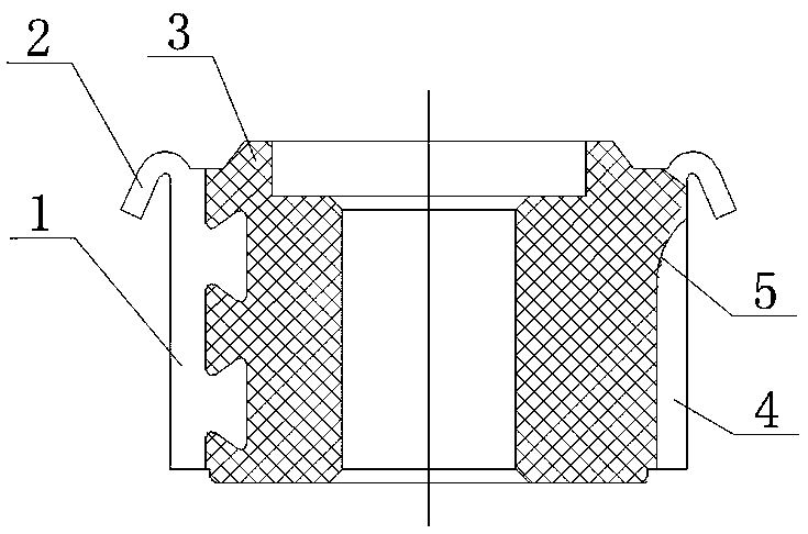
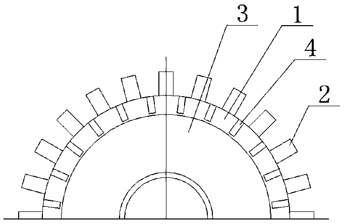
[0018] Such as figure 1 , 2 As shown, the hook-shaped commutator made of the copper sheet of the hook-shaped commutator of the present invention is composed of a bakelite powder matrix 3 and twenty-four pieces of commutators arranged in a circle on the outer circle of the bakelite powder matrix 3 Composed of copper sheets 1, the top of the reversing copper sheet 1 is provided with a hook 2, the reversing copper sheet 1 and the bakelite powder matrix 3 are integrally injection molded, and the adjacent reversing copper sheets 1 are milled out with a disc milling cutter for insulation The slot 4 is used for inter-chip insulation, and the top of the insulating slot 4 passes through a circular arc transition 5 without being milled through.

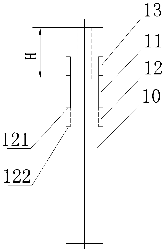
[0019] Such as Figure 3-5 As shown, the hook-type commutator copper sheet of the present invention has a bar-shaped body 10, the outer surface of the bar-shaped body 10 is a circular arc surface, and the inner surface is provided with two up...


PUM


Abstract

The invention discloses a hook type commutator copper. The hook type commutator copper includes a bar-shaped body, wherein an outer side surface of the bar-shaped body is an arc surface, and an innerside surface is a hook pin. The hook type commutator copper is characterized in that left and right side surfaces of the bar-shaped body are provided with punching gaps close to the upper portion, lower punching surfaces of the punching gaps are inclined surfaces, and the tangent height of the lower punching surfaces of the punching gaps on the outer side surface of the bar-shaped body is made tobe greater than the tangent height on the inner side surface by the inclined surfaces. The hook type commutator copper is advantaged in that the glue is prevented from entering an insulation groove, both sides of a milling slot almost have no electric wood powder hanging, appearance is good, the milling work amount is reduced, and tool wear is further reduced.

Description

technical field [0001] The invention relates to the technical field of commutators, in particular to a commutation copper sheet of a hook-type commutator. Background technique [0002] Hook-type commutator, including bakelite powder matrix and commutation copper sheets arranged around the outer circle of the bakelite powder matrix, the top of the commutation copper sheet is provided with a welding wire hook, the commutation copper sheet The powder matrix is ​​integrally injection molded. The hook type commutator has mica and no mica. The mica commutator is used to insulate the adjacent commutation copper sheets by setting mica sheets. The adjacent commutation copper sheets are insulated by milling out. The mica-free commutator is used for the inter-chip insulation. In order to prevent the glue from entering the insulation groove when the motor rotor coil is glued, some insulation grooves of the mica-free commutator require that the upper end cannot be milled through. For t...

Claims


Application Information

Patent Timeline
Patent Type & Authority Applications(China)
IPC IPC(8): H01R39/02H01R39/04
CPCH01R39/02H01R39/04
Inventor 宋泽明
Owner 瑞安市成得电器有限公司
Why Eureka
Try Eureka