Stepping linear motor with hollow shaft

A linear motor, hollow shaft technology, applied in electrical components, electromechanical devices, propulsion systems, etc., can solve the problems of cumbersome, low versatility, and difficult process, achieve good versatility, avoid process complexity, and strong flexibility. sexual effect

Pending Publication Date: 2019-10-25
SHANGHAI MOONS ELECTRICAL APPLIANCE
View PDF1 Cites 0 Cited by
  • Summary
  • Abstract
  • Description
  • Claims
  • Application Information

AI Technical Summary

Problems solved by technology

The plastic nut of this utility model needs to be produced by injection molding and extends into the interior of the rotor shaft. The process is difficult and cumbersome, and the versatility is not strong.

Method used


Image

  • Stepping linear motor with hollow shaft
  • Stepping linear motor with hollow shaft
  • Stepping linear motor with hollow shaft

Examples


Embodiment Construction

[0026] The technical solution in the embodiment of the present invention will be clearly and completely described below, obviously, the described embodiment is a module embodiment of the present invention, not all embodiments. Based on the embodiments of the present invention, all other embodiments obtained by persons of ordinary skill in the art without making creative efforts shall fall within the protection scope of the present invention.

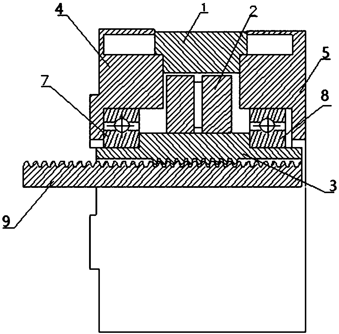
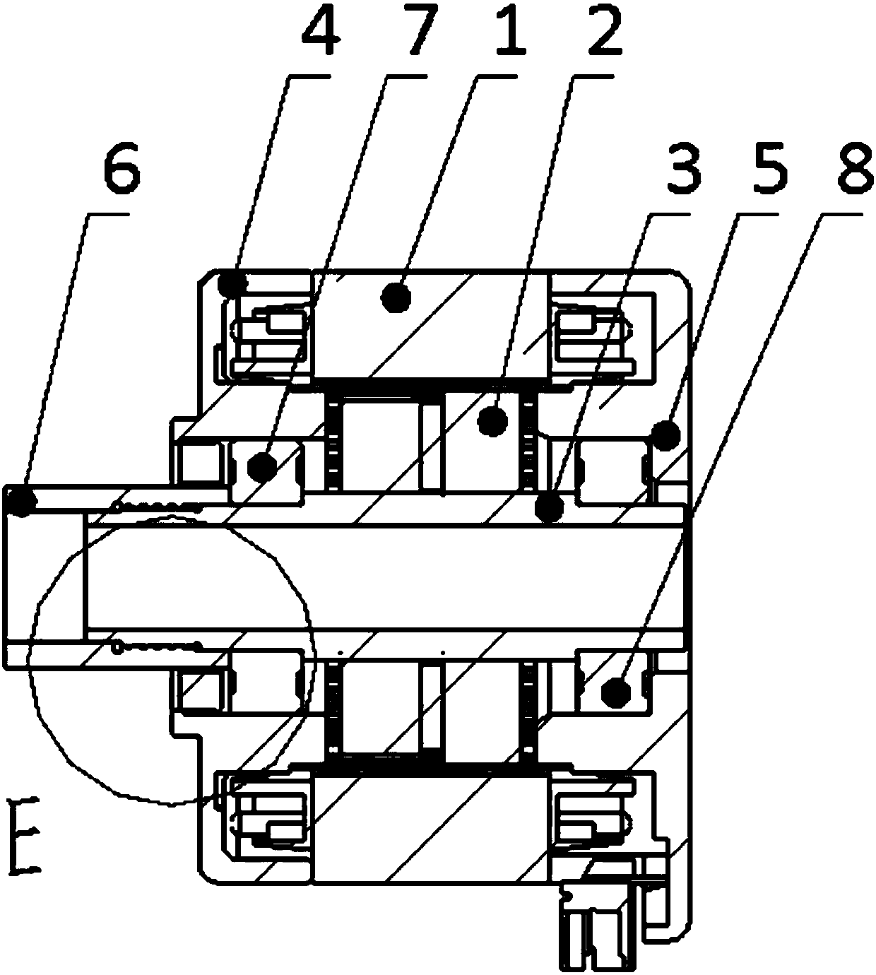
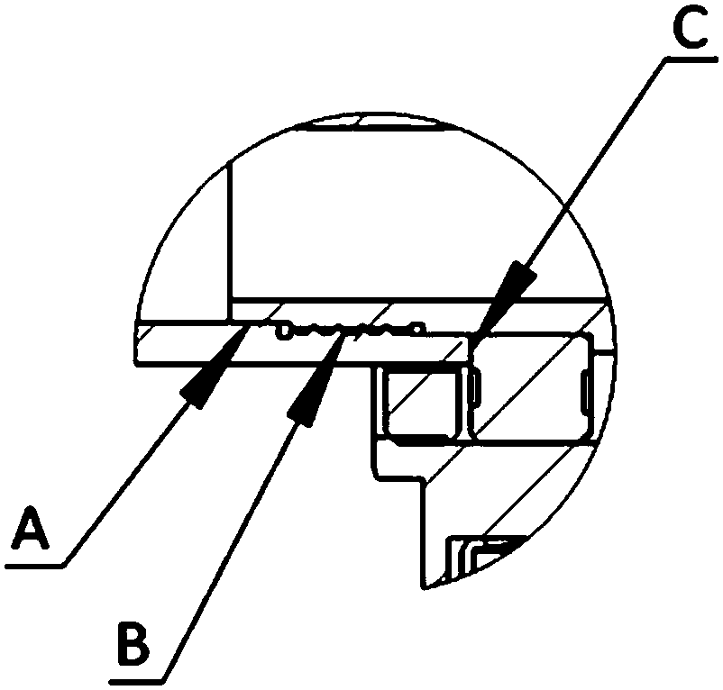
[0027] Such as figure 2 As shown, a stepping linear motor with a hollow shaft includes a stator 1, a rotor 2, a rotor shaft 3, a front end cover 4, a rear end cover 5, a front bearing 7, a rear bearing 8, and external connectors 6 or nuts, The external connecting piece 6 or the nut is connected to the rotor shaft 3, and when the motor rotates, the external connecting piece 6 or the nut is driven to move linearly. Concentric concentric mating surface A, the external connector 6 is closely connected with the rotor shaft 3 through the thr...


PUM


Abstract

The invention relates to a stepping linear motor with a hollow shaft. The motor comprises a stator, a rotor, a rotor shaft, a front end cover, a rear end cover, a front bearing, a rear bearing and anexternal connecting part or nut; the external connecting part or the nut is connected with the rotor shaft. When the motor rotates, the external connecting part or the nut is driven to rotate, and therotation is changed into linear movement through the cooperation with other screws or ball screws. The rotor shaft of the motor is provided with a threaded part matching surface used for fastening and a concentric matching surface used for centering, and the external connecting part is tightly connected with the rotor shaft through the threaded part matching surface and the concentric matching surface respectively. Compared with the prior art, the motor has the advantages of low cost, high concentricity, good universality and the like.

Description

technical field [0001] The invention relates to the field of motor structure, in particular to a step linear motor with a hollow shaft. Background technique [0002] A stepping linear motor is a motor that converts rotary motion into linear motion through a screw. An existing technology is to make the inside of the rotating rotor shaft into an internal thread structure, and then insert the screw to realize the forward and backward movement of the screw when the motor rotates. figure 1 shown. figure 1 As shown in , 1 is the stator, 2 is the rotor, 3 is the rotor shaft, 4 is the front end cover, 5 is the rear end cover, 7 is the front bearing, 8 is the rear bearing, and 9 is the screw rod. However, threading directly inside the rotor shaft will shorten the life of the rotor, and the process of threading inside the rotor shaft is difficult and cumbersome, which is not suitable for various customization requirements of customers. [0003] Another approach is to find a way to ...

Claims


Application Information

Patent Timeline
IPC IPC(8): H02K41/03H02K7/06
CPCH02K41/03H02K7/06
Inventor 邹一明曾凯刘光玉袁武锋杨文思张明生
Owner SHANGHAI MOONS ELECTRICAL APPLIANCE
Why Eureka
Try Eureka