Plate punching die

A punching and die technology, used in punching tools, manufacturing tools, metal processing equipment, etc., can solve the problems of small punching force transmission area, weak punch strength, strong pressure, etc., to reduce the mold repair rate, punch The effect of strength improvement and mass productivity improvement

Inactive Publication Date: 2019-10-29
TIANJIN SAMSUNG ELECTRONICS CO LTD +1
View PDF9 Cites 0 Cited by
  • Summary
  • Abstract
  • Description
  • Claims
  • Application Information

AI Technical Summary

Problems solved by technology

[0003] The punch of the existing punching die is a straight-through structure, the front end of the punch is matched with the unloading plate, and the unloading backing plate is used to hide the space and avoid the upper end. The diameter of the existing punch is too small, and the length of the punch is generally about 70mm. The small and slender punch is weak in strength, the transmission area of ​​punching force is small, and the pressure is high, which will easily cause the punch to break and the die to be easily damaged; the broken punch has the risk of crushing the die and breaking the template , resulting in high mold repair frequency

Method used


Image

  • Plate punching die
  • Plate punching die
  • Plate punching die

Examples


Embodiment Construction

[0020] The present invention will be described in further detail below in conjunction with the accompanying drawings and specific embodiments. It should be understood that the specific embodiments described here are only used to explain the present invention, not to limit the present invention.

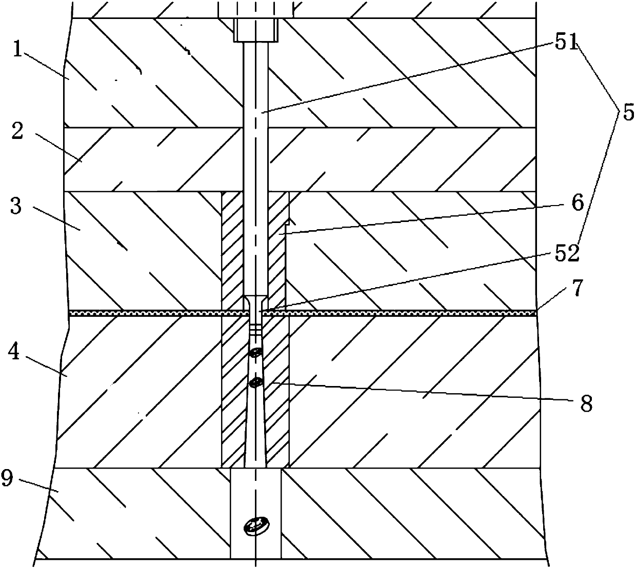
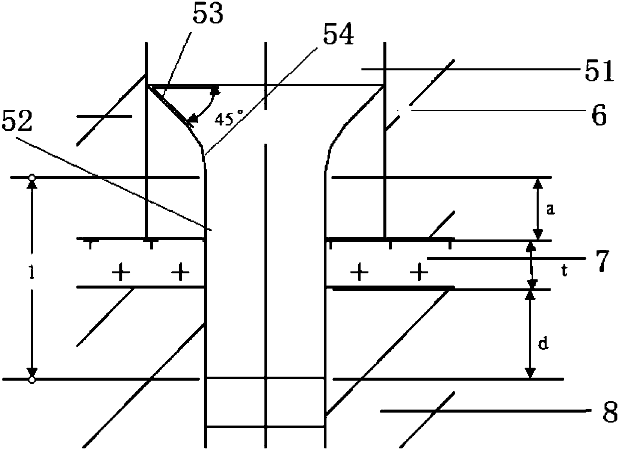
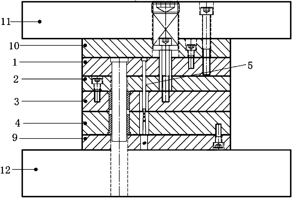
[0021] see Figure 1-3 As shown, a plate punching die includes a punch backing plate 10 and a punch 5 fixed on the punch backing plate through a punch fixing plate 1. There is a discharge material under the punch backing plate 1. Backing plate 2, the lower end of described discharging backing plate is connected with unloading plate 3, and the below of described unloading plate 3 is the concave template 4 that is fixed on the die backing plate 9; Described punch comprises base body portion 51 and diameter To the concentric punching working part 52 whose size is smaller than that of the base part, a cylindrical stripping plate insert 6 is installed in the stripping plate 3 to provide a...


PUM


Abstract

The invention discloses a plate punching die. The plate punching die comprises a punch base plate and a punch fixed on the punch base plate through a punch fixing plate, wherein a discharging base plate is arranged below the punch base plate, the lower end of the discharging base plate is connected with a discharging plate, the lower portion of the discharging plate is a female die plate fixed ona female die base plate, the punch comprises a base body portion and a coaxial punching working portion with the radial size smaller than that of the base body portion, and a cylindrical discharging plate insert for providing guide for punch motion is installed in the discharging plate. According to the plate punching die, the strength of the punch is effectively improved, the service life of thepunch female die is prolonged, so that the yield of the thick plate punched hole is remarkably improved, and the die repair rate is reduced.

Description

technical field [0001] The invention relates to the technical field of punching dies, in particular to a plate punching die. Background technique [0002] In the development process of new TV products, the TV stand part needs iron parts with a material thickness of 4.0mm as support, and a round hole of Φ3.6 needs to be punched on the iron parts. The relationship between t is generally D>1.5t to ensure the service life of the punch; and the newly designed product has a hole diameter smaller than the material thickness, which is not included in the conventional punching range, and belongs to the thick plate punching small hole. ≤Material thickness t. [0003] The punch of the existing punching die is a straight-through structure, the front end of the punch is matched with the unloading plate, and the unloading backing plate is used to hide the space and avoid the upper end. The diameter of the existing punch is too small, and the length of the punch is generally about 70mm...

Claims


Application Information

Patent Timeline
IPC IPC(8): B21D28/34
CPCB21D28/34
Inventor 唱明明
Owner TIANJIN SAMSUNG ELECTRONICS CO LTD
Why Eureka
Try Eureka