
Manufacturing method and transporting method of steel box girder with high crossbeam

A technology of manufacturing method and transportation method, which is applied in the direction of bridges, bridge construction, erection/assembly of bridges, etc., can solve the problems of difficult matching of parts, prolonging the construction period, and restricting the transportation of box girder sections, so as to reduce the height and improve the stability Effect

Inactive Publication Date: 2019-10-29
CHINA RAILWAY HEAVY MACHINERY
View PDF8 Cites 1 Cited by
  • Summary
  • Abstract
  • Description
  • Claims
  • Application Information

AI Technical Summary

Problems solved by technology

[0002] Steel box girder is a common structural form of long-span bridges. With the increase of municipal steel box span, the girder height will also be greatly increased, so that the girder height requirement of the existing municipal steel box will reach 6-9m, while the current Some municipal and high-speed roads have a maximum transportation height limit of 4.5 meters, which greatly limits the transportation of high-girder box girder segments, making it difficult to transport steel box girders with high girders to the site for operation
[0003] At present, the existing on-site installation method of girder and high-steel box girder mainly adopts the form of transportable plate unit made in the factory, then transported by car, and the box girder is assembled and formed on the project site through loose assembly. However, there are many methods for this method. Disadvantages: First, the structures manufactured in the factory are mostly in the form of plate units or rods. Since there is no stable force-bearing structure during batch transportation, unpredictable force deformation is prone to occur during transportation. Difficult to match; second, it is difficult to guarantee the on-site positioning accuracy of large-scale plate units, and it is necessary to install a stable structure during assembly. The demand is large, and at the same time, the requirements for the overall assembly site are high, and the construction period is also extended

Method used


Image

  • Manufacturing method and transporting method of steel box girder with high crossbeam
  • Manufacturing method and transporting method of steel box girder with high crossbeam
  • Manufacturing method and transporting method of steel box girder with high crossbeam

Examples


Embodiment 1

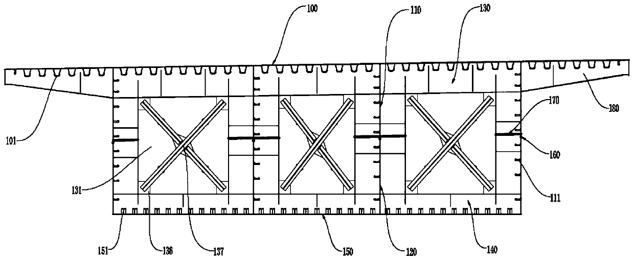
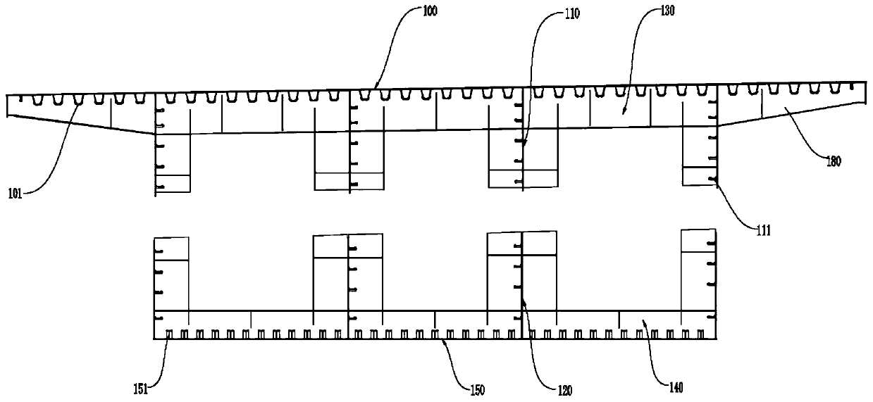
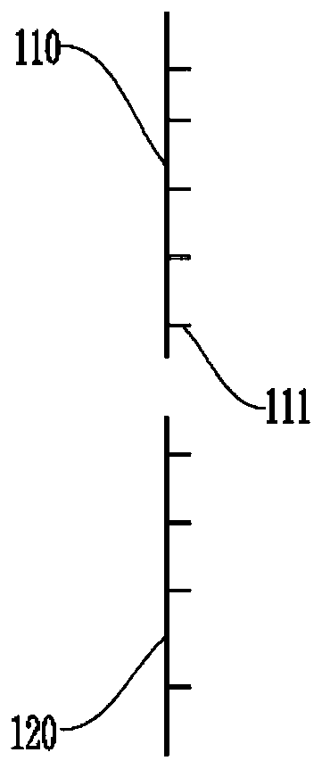
[0061] The embodiment of the present application provides a method for transporting a large girder and a high steel box girder, which includes the following steps:

[0062] Please refer to figure 1 , figure 2 , image 3 , Figure 4 As shown, the top plate 100, bottom plate 150, four upper webs 110, four lower webs 120 corresponding to the upper webs 110, three upper partitions 130 and three upper partitions 130 are manufactured respectively. The lower partition 140; wherein, the top plate 100 is prepared by splicing five pre-manufactured top plate units; the bottom plate 150 is prepared by splicing four pre-manufactured bottom plate veneers, and the bottom of the top plate 100 is also connected with thirty Eight U-shaped stiffeners 101 are arranged parallel to each other at intervals. Thirty-five T-shaped stiffeners 151 are connected to each other at intervals on the top of the bottom plate unit. One side of the upper web 110 is connected with five parallel and vertical ri...


PUM


Abstract

The invention provides a manufacturing method and transporting method of a steel box girder with a high crossbeam and relates to the technical field of box girders. The transporting method of the steel box girder with the high crossbeam comprises the following steps that an upper portion steel box girder and a lower portion steel box girder are manufactured; the upper portion steel box girder comprises a top plate, multiple upper webs and multiple upper partition plates, the multiple upper webs and the multiple upper partition plates are fixed to the bottom of the top plate, the lower portionsteel box girder comprises a bottom plate, multiple lower webs and multiple lower partition plates, and the multiple lower webs and the multiple lower partition plates are fixed to the top end of thebottom plate; the upper portion steel box girder and the lower portion steel box girder are transported to the site and connected vertically to form the steel box girder, the upper webs and the corresponding lower webs are connected vertically to form a web, and the upper partition plates and the corresponding lower partition plates are connected vertically to form a partition plate; and when theupper portion steel box girder is transported, multiple supporting cylinders with hydraulic jacks arranged on the tops are used for supporting the upper portion steel box girder onto a vehicle. According to the manufacturing method and transporting method of the steel box girder with the high crossbeam, the upper portion steel box girder and the lower portion steel box girder are manufactured correspondingly and transported to the site and spliced to obtain the steel box girder with the high cross beam, the splicing precision of the steel box girder is improved, and the construction period isshortened.

Description

technical field [0001] The present application relates to the field of box girders, in particular, to a manufacturing method and transportation method of a girder high steel box girder. Background technique [0002] Steel box girder is a common structural form of long-span bridges. With the increase of municipal steel box span, the girder height will also be greatly increased, so that the girder height requirement of the existing municipal steel box will reach 6-9m, while the current Some municipal and high-speed roads have a maximum transportation height limit of 4.5 meters, which greatly limits the transportation of high-girder box girder segments, making it difficult to transport high-girder steel box girders to the site for operation. [0003] At present, the existing on-site installation method of girder and high-steel box girder mainly adopts the form of transportable plate unit made in the factory, then transported by car, and the box girder is assembled and formed on...

Claims


Application Information

Patent Timeline
Patent Type & Authority Applications(China)
IPC IPC(8): E01D21/00E01D2/04
CPCE01D2/04E01D21/00
Inventor 季轩夏一飞李潭张俊沈强刘贝贝赵斌全顺红陈小山肖雄兵张威王斌
Owner CHINA RAILWAY HEAVY MACHINERY
Learn More