Patch position error detection method based on digital image

A digital image and error detection technology, which is applied in image enhancement, image analysis, image data processing, etc., can solve the problems of not meeting the requirements of fast production and high time cost, and achieve the improvement of template matching speed, extraction speed and noise reduction interference effect

Inactive Publication Date: 2019-10-29
ZHEJIANG UNIV
View PDF3 Cites 0 Cited by
  • Summary
  • Abstract
  • Description
  • Claims
  • Application Information

AI Technical Summary

Problems solved by technology

Among them, the classic Canny feature extraction method needs to calculate the gradient direction value of all points on the non-maximum value suppression algorithm, and perform interpolation operation to judge whether the point is the maximum value of the gradient direction; whi

Method used


Image

  • Patch position error detection method based on digital image
  • Patch position error detection method based on digital image
  • Patch position error detection method based on digital image

Examples


Example Embodiment

[0048] The present invention will be described in further detail below in conjunction with the accompanying drawings and specific embodiments. Embodiments of the present invention and its implementation process are as follows:

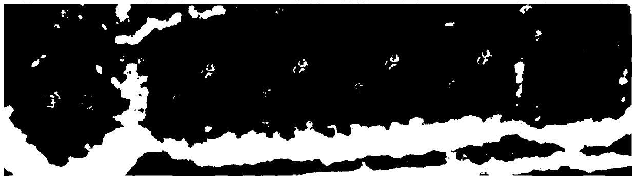
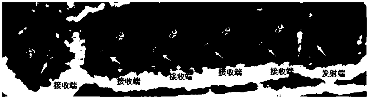
[0049] The optical fiber transceiver PCB board processed by the embodiment of the present invention is photographed by an industrial camera and obtained as follows: figure 1 As shown, it includes 5 receiver chips and 1 transmitter chip such as figure 2 shown. In order to make the above chips and optical fibers with equal distances butt joints, it is required that the positions of the above six chips are equally spaced. The four center points on the center wafer have been arranged at equal intervals, so it is necessary to detect whether the left and right center points meet the error requirements.

[0050] 1) The weighted mean filter is used to denoise the image, and the image histogram equalization is used to improve the image contrast, and the impro...


PUM


Abstract

The invention discloses a patch position error detection method based on a digital image. The method comprises the following steps: 1) denoising an image by adopting a weighted mean filter, improvingthe image contrast by adopting image histogram equalization, and extracting image edge features by adopting an improved Canny algorithm; 2) intercepting a template and recording a matching standard point, and carrying out template matching by adopting an improved SAD algorithm (absolute error sum) according to the result of the step 1); and 3) finally, finding a matching standard point by applyingthe matching standard point offset vector, and further calculating the patch position error based on the digital image. According to the patch position error detection method based on the digital image, patch edge features and position features based on the digital image are fully combined, and patch position error detection can be completed quickly and accurately.

Description

technical field [0001] The invention relates to a position error detection method, in particular to a digital image-based patch position error detection method. Background technique [0002] In the process of producing optical fiber transceiver PCB boards, it is necessary to use an automatic placement machine for dispensing and placement on the PCB board. In actual production, due to the high positioning accuracy of product placement, the traditional automatic placement machine cannot guarantee that the placement accuracy meets the manufacturer's requirements. Therefore, after the chip placement process, the chip position detection must be carried out, and the traditional chip position detection mainly relies on manual operation detection, which not only has low work efficiency, but also has large detection errors, so the manual detection method can no longer meet the large-scale production of optical fiber transceiver PCB boards. Require. [0003] The traditional feature ...

Claims


Application Information

Patent Timeline
IPC IPC(8): G06T7/00G06T7/13G06T7/136G06T7/73G06K9/62G06T5/00G06T5/40
CPCG06T7/0004G06T7/13G06T7/136G06T7/73G06T5/002G06T5/40G06T2207/10004G06T2207/30141G06V10/751
Inventor 何衍张吉春张森林刘妹琴樊臻郑荣濠
Owner ZHEJIANG UNIV
Why Eureka
Try Eureka