
Wafer processing method

A processing method and chip technology, applied in metal processing equipment, manufacturing tools, laser welding equipment, etc., can solve problems such as device defects, quality degradation, and difficult positioning of pressing blades, and achieve the effect of overcoming quality degradation

Pending Publication Date: 2019-10-29
DISCO CORP
View PDF1 Cites 0 Cited by
  • Summary
  • Abstract
  • Description
  • Claims
  • Application Information

AI Technical Summary

Problems solved by technology

However, when the division line is formed by dividing along the division starting point of the first planned division line, the adhesive layer enters the division line, etc., causing the undivided second planned division line to bend slightly, making it difficult to move along the second planned division line. The pressing blade is precisely positioned on the planned dividing line. In this case, when the pressing blade is positioned and an external force is applied to divide the second planned dividing line, there is a problem that chipping of the device occurs, resulting in a decrease in quality.

Method used


Image

  • Wafer processing method
  • Wafer processing method
  • Wafer processing method

Examples


Embodiment Construction

[0022] Hereinafter, each step of the wafer processing method according to the present invention will be described in order.

[0023] (Polyester sheet laying process)

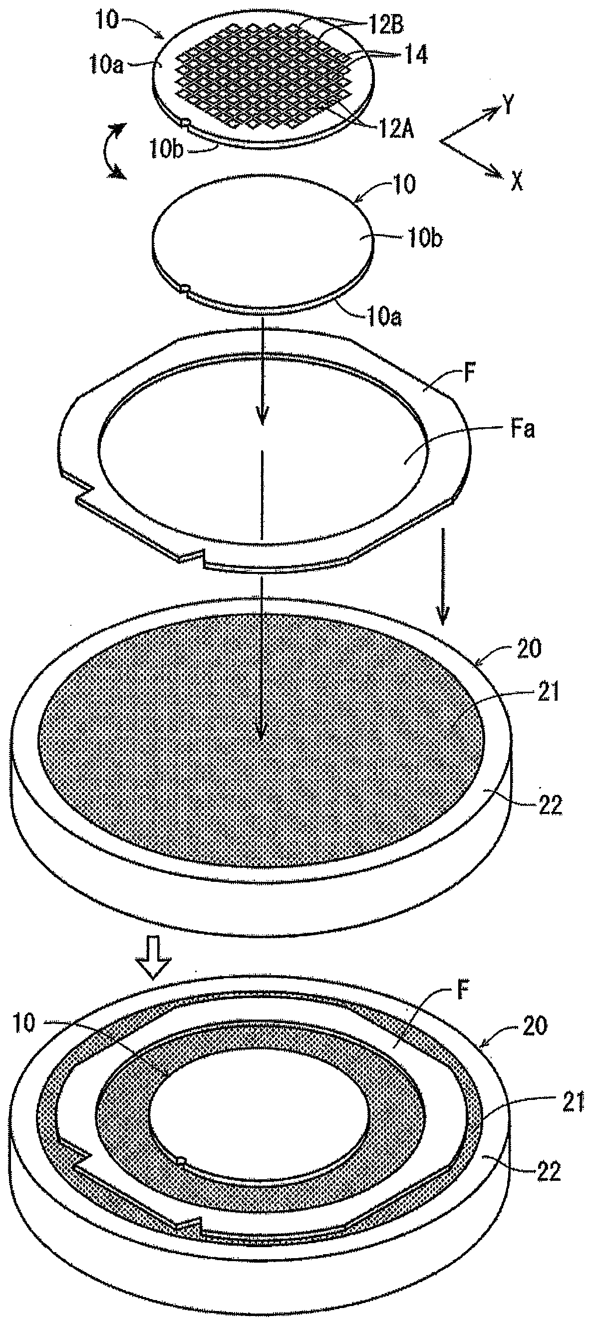
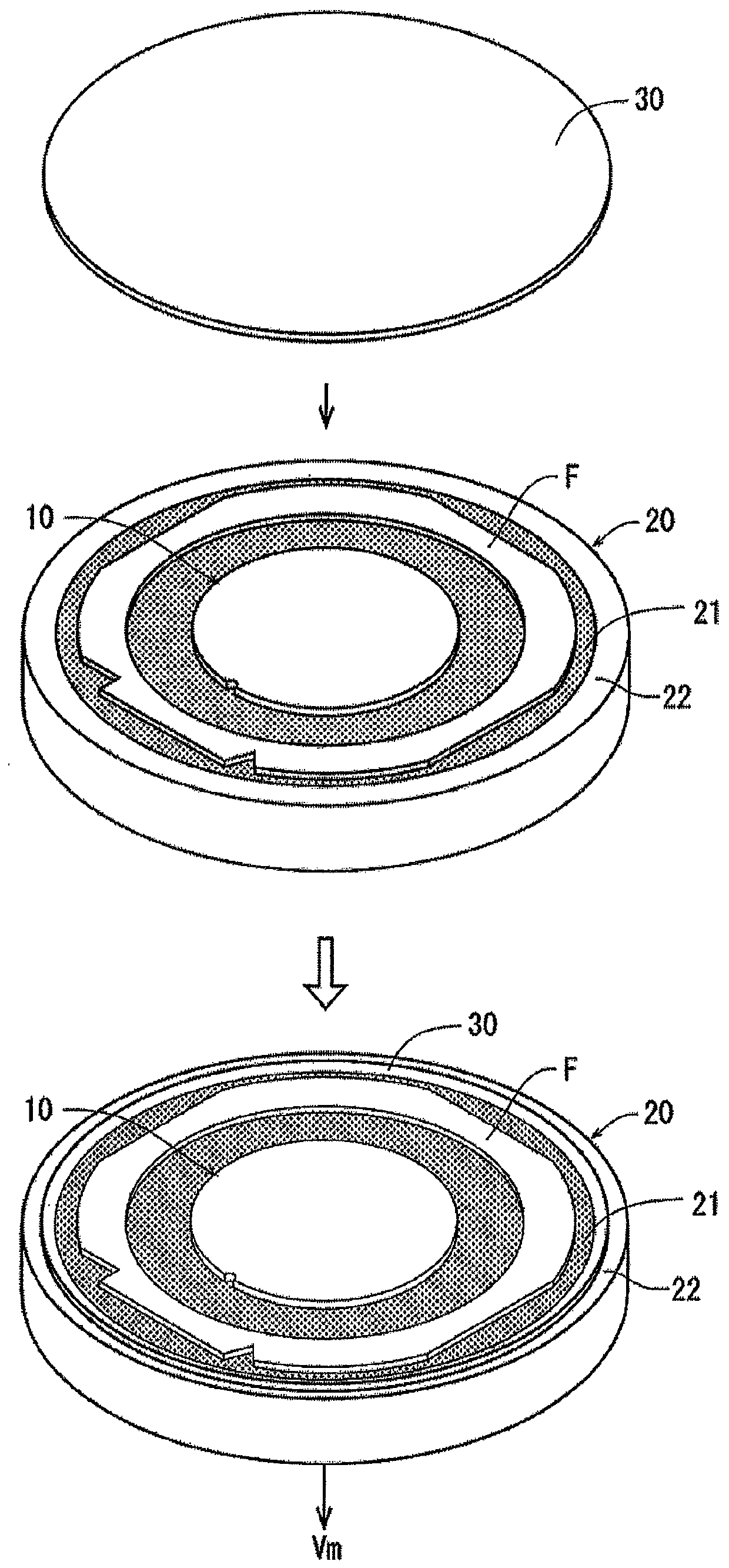
[0024] refer to figure 1 and figure 2 , and the polyester-based sheet laying process will be described. exist figure 1 A perspective view of an embodiment of the polyester-based sheet laying step is shown in . When implementing the laying process of polyester sheets, first of all, as figure 1 As shown, a wafer 10 as an object to be processed, a ring frame F having an opening Fa capable of accommodating the wafer 10 , and a chuck table 20 for performing a polyester-based sheet laying process are prepared. The wafer 10 is made of, for example, a silicon (Si) substrate, and the devices 14 are formed on a first planned division line 12A formed along a first direction indicated by an arrow X and a second line indicated by an arrow Y intersecting at right angles to the first direction. On the front side 10a div...


PUM

PropertyMeasurementUnit
thicknessaaaaaaaaaa

Abstract

Provided is a wafer processing method without degrading device quality. The wafer processing method comprises at least the following steps: the polyester-based sheet laying step of positioning the wafer in the opening of a frame having an opening for accommodating the wafer, and laying a polyester-based sheet on the back surface of the wafer and the outer periphery of the frame; the integrated step of heating the polyester-based sheet and performing thermocompression-bonded to integrate the wafer and the frame through the polyester-based sheet; the division starting point forming step of positioning the light-condensing point of the laser beam at the first predetermined division line and the second division a predetermined line and irradiating to form a dividing starting point; the first division step of positioning the pressing blade at the first dividing predetermined line and applying an external force to divide the first dividing predetermined line; and the second division step ofpositioning the pressing blade at the second division predetermined line and applying an external force to divide the second division predetermined lines, wherein the wafer is divided into individualdevices by the first division step and the second division step.

Description

technical field [0001] The present invention relates to a method of processing a wafer, which is divided into individual devices. Background technique [0002] Wafers divided by planned division lines and formed with multiple devices such as ICs, LSIs, and LEDs on the front surface are divided into individual devices by dicing equipment, laser processing equipment, etc., and are used in electronic equipment such as mobile phones and personal computers. [0003] There are following types of laser processing apparatuses: the focus point of the laser beam having a transparent wavelength to the wafer is positioned at the inside of the planned dividing line and irradiated to form a modified layer as the starting point of dividing (for example, refer to Patent Document 1): A type in which a laser beam with an absorbing wavelength is positioned on the upper surface of a planned line for division and irradiated, and a groove is formed on the front side by ablation as a starting poin...

Claims


Application Information

Patent Timeline
Patent Type & Authority Applications(China)
IPC IPC(8): H01L21/304H01L21/67H01L21/78
CPCH01L21/78H01L21/67253H01L21/304H01L21/76H01L21/187H01L21/02118H01L21/324B23K26/38
Inventor 荒川太朗冈村卓
Owner DISCO CORP
Learn More