An Omnidirectional Scanning End-Fire Array Antenna with Horizontal Beam

A horizontal beam and antenna technology, applied in the field of omnidirectional scanning end-fire array antennas, can solve the problems of not having scanning capability, not involving end-fire array beam upturns, and not giving end-fire array beam upturns, etc. Simple, high-gain, simple-architecture effects

Active Publication Date: 2021-08-06
CHINA ELECTRONIC TECH GRP CORP NO 38 RES INST
View PDF4 Cites 0 Cited by
  • Summary
  • Abstract
  • Description
  • Claims
  • Application Information

AI Technical Summary

Problems solved by technology

There is also a certain research foundation for end-fire array antennas in China. The team of Professor Xue Zhenghui of Beijing Institute of Technology uses Yagi antennas as the antenna unit of end-fire arrays, which can achieve high-gain design, but does not have scanning capabilities; the team of Professor Yang Shiwen of University of Electronic Science and Technology of China has applied for A patent on an omnidirectional scanning endfire array antenna, but its research focus is on a novel low-profile endfire array antenna unit, and does not involve the solution of the beam upturning problem of a finite large endfire array (Yao Guowei, Xue Zhenghui, Li Weiming, Ren Wu. "Design of End-fire Phased Array Antenna", Beijing: Journal of China Institute of Electronic Science, 2010; Yang Shiwen, Wang Fang, Chen Yikai, Xiao Shiwei, Liu Kunning, Qu Shiwei. A low-profile omnidirectional scanning end-fire antenna Array, Chinese invention patent, 2017.4, application number: 201710236613.9.)
[0004] To sum up, in the existing research on the application and technology of end-fire array antennas, a good solution to the beam upwarping of end-fire arrays in engineering applications has not been given, and the effective solution to the problem of beam upwarping Solving is the key to realize mature engineering application of end-fire array antenna

Method used


Image

  • An Omnidirectional Scanning End-Fire Array Antenna with Horizontal Beam
  • An Omnidirectional Scanning End-Fire Array Antenna with Horizontal Beam
  • An Omnidirectional Scanning End-Fire Array Antenna with Horizontal Beam

Examples


Embodiment Construction

[0028] In order to have a further understanding and understanding of the structural features of the present invention and the achieved effects, the preferred embodiments and accompanying drawings are used for a detailed description, as follows:

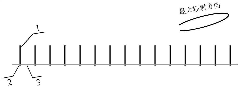
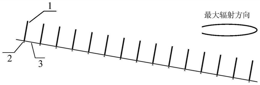
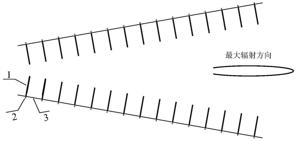
[0029] Such as figure 1 , figure 2 , image 3 As shown, a horizontal beam omni-directional scanning end-fire array antenna is composed of a plurality of unit modules whose axes are concentric to the center of the circle, and the number of unit modules contained in it is ≥ 1, and the minimum number of unit modules required is 360° divided by Take the 3dB beam width of the azimuth plane beam of the unit module, and round up if it cannot be divisible by an integer. The unit module includes two end-fire array antenna sub-arrays, and the two end-fire array antenna sub-arrays are tilted according to the angle of upturning of the beam of the end-fire array antenna sub-array, and the array is in the shape of a "V" to form a unit module; th...


PUM


Abstract

The present invention provides an omnidirectional scanning end-fire array antenna with a horizontal beam, which includes a plurality of unit modules, and the plurality of unit modules are radially and uniformly arranged on the same axis as the center of the circle; the unit modules include two end-fire array antenna sub-arrays, two An end-fire array antenna sub-array is in the shape of a "V" to form a unit module; the "V"-shaped angle of the unit module faces the center of the circle or the opening faces the circle; the end-fire array antenna sub-array includes antenna units, the same unit The two end-fire array antenna sub-array antenna units in the module are arranged opposite to each other. Compared with the prior art, the present invention provides an end-fire array antenna with simple structure, high gain, horizontal beam, and 360° omnidirectional scanning in the azimuth plane. The end-fire array antenna sub-array is tilted and the beams are superimposed to realize the end-fire beam of horizontal radiation, which can effectively solve the problem of the beam upturning of the end-fire array, and provides a good solution for the engineering application of the end-fire array.

Description

technical field [0001] The invention belongs to the technical field of end-fire array antennas, and in particular relates to an omnidirectional scanning end-fire array antenna with a horizontal beam. Background technique [0002] Due to its electrical scanning characteristics, phased array antennas are widely used in radar and communication fields. In the existing phased array antenna research, most of them focus on the side-firing array. Its radiation direction is the normal direction of the array arrangement, perpendicular to the metal floor, and the maximum beam pointing will not be deflected by the influence of the metal floor. , the technical research of the side-firing array has been relatively mature. Different from the side-fire array, the maximum radiation direction of the end-fire array antenna is along the axis of the array instead of the normal direction, and its theoretical maximum radiation direction is parallel to the metal floor, but it is affected by the me...

Claims


Application Information

Patent Timeline
Patent Type & Authority Patents(China)
IPC IPC(8): H01Q21/06H01Q1/48H01Q1/50
CPCH01Q1/48H01Q1/50H01Q21/06
Inventor 邹文慢金谋平方佳张小林王泉
Owner CHINA ELECTRONIC TECH GRP CORP NO 38 RES INST
Why Eureka
Try Eureka