A kind of processing method of deep cavity clearing angle

A processing method and deep cavity technology, applied in metal processing equipment, manufacturing tools, milling machine equipment, etc., can solve the problems of inability to meet the processing requirements of waveguide parts, unattainable R angle roughness, poor R angle surface roughness, etc. Achieve the effect of improving material removal rate, improving stability and efficiency, and ensuring strength

Active Publication Date: 2020-11-24
HUBEI SANJIANG SPACE XIANFENG ELECTRONICS&INFORMATION CO LTD
View PDF7 Cites 0 Cited by
  • Summary
  • Abstract
  • Description
  • Claims
  • Application Information

AI Technical Summary

Problems solved by technology

The main reasons are: a) The smaller the diameter of the drill bit, the lower the strength, and the higher the probability of the drill bit breaking during the drilling process, the tool will remain in the drilled hole after breaking and it is difficult to take it out; b) The R-angle surface processed by the drilling method The roughness is poor, and the best can only reach Ra3.2 after reaming, and there will be residues at both ends of the processed R angle, so the roughness of the R angle processed by this patent cannot reach Ra1.6, which cannot meet the requirements of the waveguide. Processing requirements for similar parts

Method used


Image

  • A kind of processing method of deep cavity clearing angle
  • A kind of processing method of deep cavity clearing angle
  • A kind of processing method of deep cavity clearing angle

Examples


Embodiment Construction

[0030] In order to make the object, technical solution and advantages of the present invention clearer, the present invention will be further described in detail below in conjunction with the accompanying drawings and embodiments. It should be understood that the specific embodiments described here are only used to explain the present invention, not to limit the present invention.

[0031] In addition, the technical features involved in the various embodiments of the present invention described below can be combined with each other as long as they do not constitute a conflict with each other.

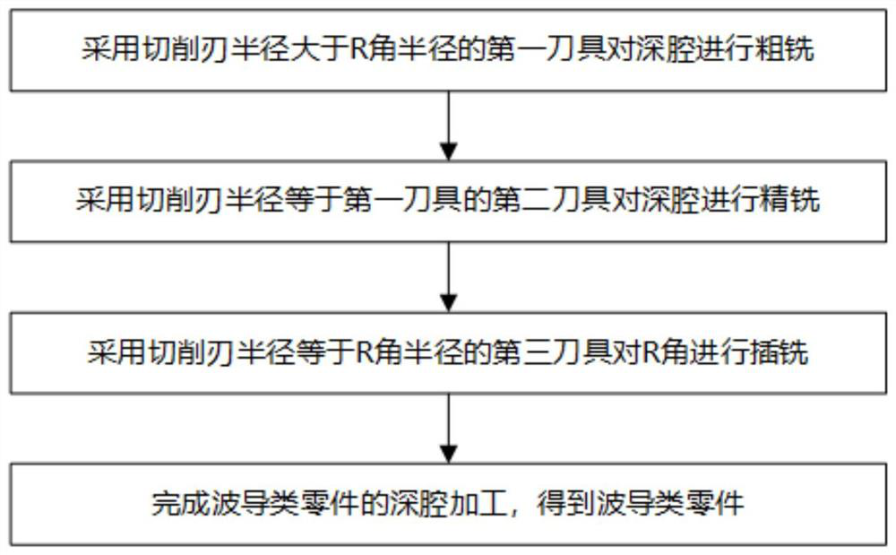
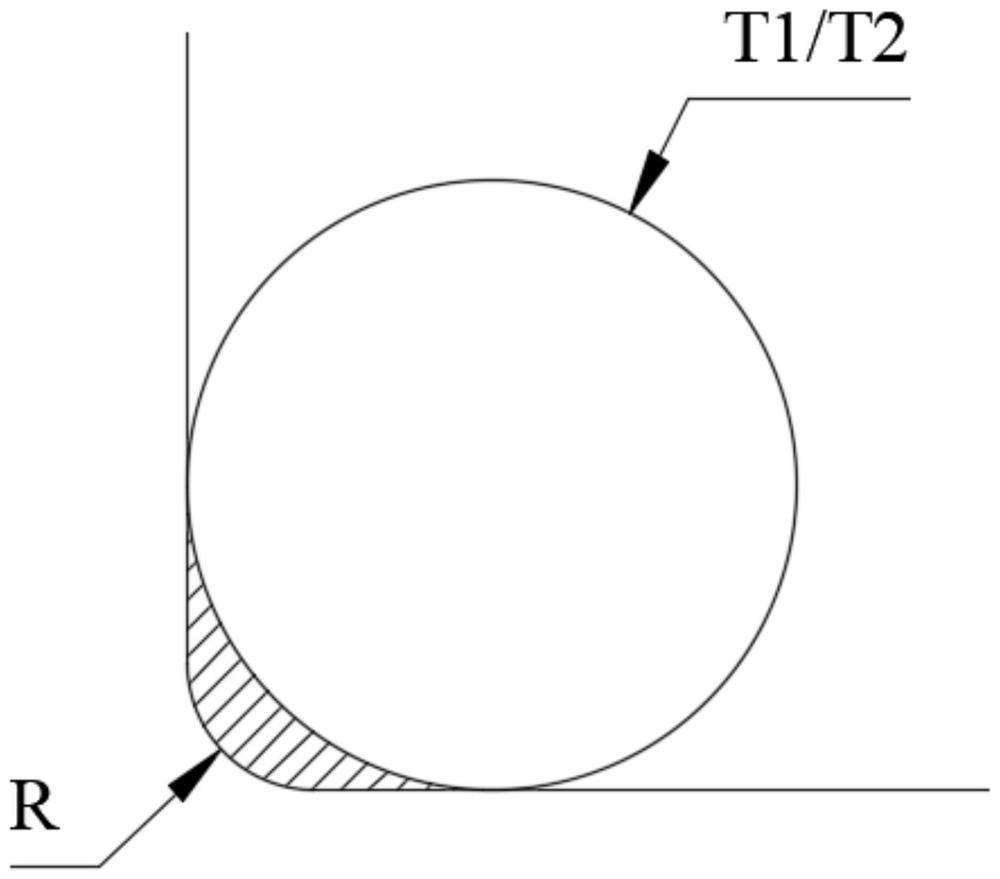
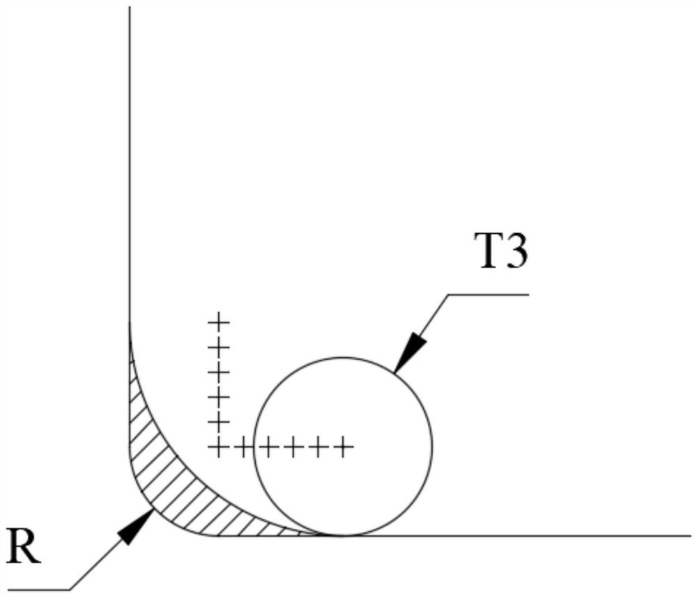
[0032] The deep cavity angle-clearing processing method for waveguide parts in the present invention aims to reduce the probability of tool breakage while improving the efficiency of deep cavity processing at the R angle in the waveguide groove, ensuring the stability of the tool processing state, so that the R angle of the waveguide groove The roughness reaches Ra1.6. For this reason,...


PUM


Abstract

The invention discloses a processing method for a deep cavity clear angle, belonging to the technical field of machining, comprising the following steps: S1: performing rough milling on all parts of adeep cavity by using a first tool having a cutting edge radius larger than the radius of an R angle; S2 : performing finish milling on all parts of the deep cavity by using a second tool having the cutting edge radius equal to the radius of the first tool; S3: performing plunge milling on the R angle region after finish milling by using a third tool having the cutting edge radius not greater thanthe radius of the R angle to complete the deep cavity processing of the R angle. By using the processing method for the deep cavity clear angle, the processing efficiency and quality of a waveguide groove of a waveguide component can be effectively improved, the damage of the tools can be reduced, the roughness after processing of the waveguide groove can be ensured, the production cost of the waveguide component can be reduced, and the method has good application and promotion values.

Description

technical field [0001] The invention belongs to the technical field of mechanical processing, and in particular relates to a processing method for clearing corners of deep cavities. Background technique [0002] With the continuous development of science and technology, the application of waveguide components is becoming more and more extensive. In order to ensure the stable transmission of microwaves in the waveguide groove, it is generally required that the fillet in the waveguide groove be as small as possible (generally the fillet requires R≤0.5), and the overall surface roughness of the waveguide groove is relatively high, with a minimum requirement of Ra1.6. [0003] Therefore, when finishing waveguide parts, it is necessary to use a tool with a tool radius ≤ fillet R of the waveguide groove to adapt. When the ratio of the depth of the waveguide groove to the R value of the inner fillet is greater than or equal to 20, that is, the length-to-diameter ratio of the requi...

Claims


Application Information

Patent Timeline
Patent Type & Authority Patents(China)
IPC IPC(8): B23C3/12
CPCB23C3/12B23C2220/605
Inventor 刘朝阳王晓伟贾凯
Owner HUBEI SANJIANG SPACE XIANFENG ELECTRONICS&INFORMATION CO LTD
Why Eureka
Try Eureka