A flexible printed substrate

A flexible printing and flexible substrate technology, applied in the direction of printed circuits, welding equipment, manufacturing tools, etc., can solve the problems of damaged display effect, insufficient soldering structure, poor soldering effect, etc., to improve connection stability and structure The effect of intensity

Active Publication Date: 2021-10-15
朱笑笑
View PDF8 Cites 0 Cited by
  • Summary
  • Abstract
  • Description
  • Claims
  • Application Information

AI Technical Summary

Problems solved by technology

The present invention is mainly used to solve the poor soldering effect of the soldering part in the existing notebook computer. During the soldering process, the internal air is easy to remain, so that the soldering structure is not strong enough, so that the display of the notebook computer is not strong enough during the long-term use. The problem that the display effect is damaged due to the opening and closing of the screen back and forth

Method used


Image

  • A flexible printed substrate
  • A flexible printed substrate
  • A flexible printed substrate

Examples


Embodiment Construction

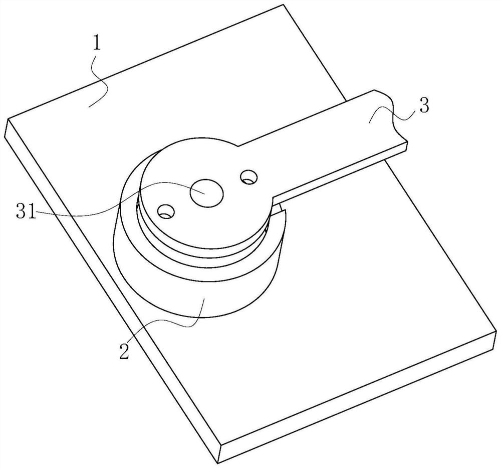
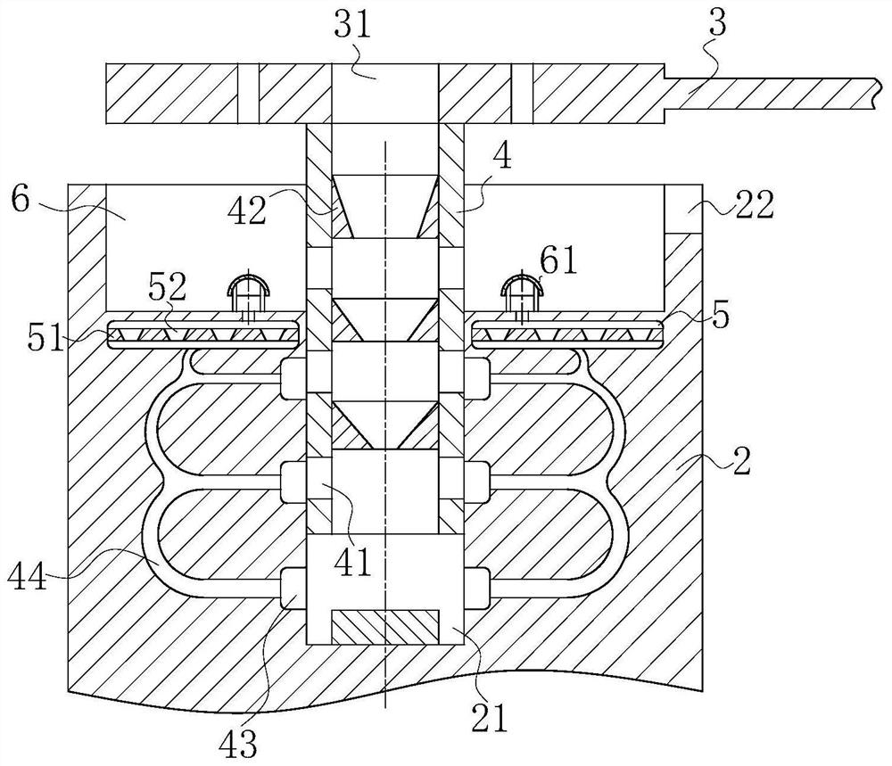
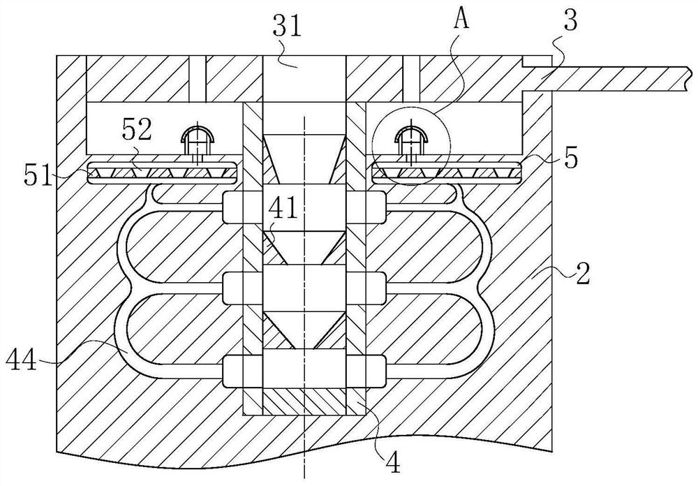
[0019] use Figure 1-Figure 4 A flexible printed board according to an embodiment of the present invention will be described below.

[0020] Such as Figure 1-Figure 4 As shown, a flexible printed substrate according to the present invention includes a bottom plate 1, a welded pipe 2, a flexible substrate 3 and a fixed pipe 4; , a limit groove 22 is set in the right end wall of the welded pipe 2; a fixed pipe 4 is inserted into the fixed groove 21; the upper end of the fixed pipe 4 is fixedly installed on the lower surface of the left end of the flexible substrate 3, and a fixed hole is provided in the fixed pipe 4 41; the left end of the flexible substrate 3 is disc-shaped, and the middle part of the flexible substrate 3 is provided with an injection hole 31; during work, if the end of the flexible substrate 3 needs to be soldered, the fixed tube at the lower end of the flexible substrate 3 can be first 4 inserted into the fixed groove 21 in the welded pipe 2, and then the ...


PUM


Abstract

The invention belongs to the technical field of computer electronic substrates, specifically a flexible printed substrate, including a bottom plate, a welded pipe, a flexible substrate and a fixed pipe; A limit slot is set in the wall; a fixed tube is inserted into the fixed slot; the upper end of the fixed tube is fixedly installed on the lower surface of the left end of the flexible substrate, and a fixed hole is opened in the fixed tube; the left end of the flexible substrate is disc-shaped, There is an injection hole in the middle of the flexible substrate; the invention is mainly used to solve the poor soldering effect of the soldering place in the existing notebook computer, and the air is easy to remain inside during the soldering process, so that the soldering structure is not strong enough, resulting in long-term use. During the process, as the display screen of the notebook computer opens and closes back and forth, the display effect is damaged.

Description

technical field [0001] The invention belongs to the technical field of computer electronic substrates, in particular to a flexible printed substrate. Background technique [0002] For example, a strain gauge for measuring the strain of a structure is formed on a very thin flexible printed circuit board, and in order to obtain an output from the strain gauge, a flexible printed circuit board for signal transmission electrically connected to an electrode of the substrate is bonded by soldering, and generally There is known a technique for soldering and joining the electrode of the former flexible printed circuit board and the opposite side electrode of the latter flexible printed circuit board. There is no special structure for releasing air to the outside during thermocompression bonding. There is a possibility that air may remain in the bonded portion during thermocompression bonding, causing peeling of the soldered bonded portion. Specifically, when the pre-solder is melte...

Claims


Application Information

Patent Timeline
Patent Type & Authority Patents(China)
IPC IPC(8): B23K3/06
CPCB23K3/0607B23K2101/42
Inventor 王育安张琼琼王章选
Owner 朱笑笑
Why Eureka
Try Eureka