Linear welding robot
A linear welding and welding machine technology, applied in the field of robots, can solve the problems of poor welding stability, low welding efficiency, and large weld seam gaps, and achieve the effects of fast welding speed, improved welding efficiency, and improved stability
- Summary
- Abstract
- Description
- Claims
- Application Information
AI Technical Summary
Problems solved by technology
Method used
Image

Examples
Embodiment 1
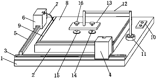
[0013] A linear welding robot comprises an installation base plate 1, a welding platform 2 is arranged in the middle of the upper surface of the installation base plate 1, a first welding machine slide rail 3 is fixed on the front side of the upper surface of the installation base plate 1, and the first A first welding machine trolley 4 is installed on the welding machine slide rail 3, a second welding machine slide rail 5 is fixed on the left side of the upper surface of the installation base plate 1, and a second welding machine slide rail 5 is installed on the second welding machine slide rail 5. Machine trolley 6, a welding trolley control switch 10 is installed on the right side of the upper surface of the installation base plate 1, and the welding trolley control switch 10 is respectively connected to the first welding machine trolley 4 and the second welding machine trolley 6. The welding platform 2 is placed with a workpiece 8, the left side and the front side of the wo...
Embodiment 2
[0015] A linear welding robot comprises an installation base plate 1, a welding platform 2 is arranged in the middle of the upper surface of the installation base plate 1, a first welding machine slide rail 3 is fixed on the front side of the upper surface of the installation base plate 1, and the first A first welding machine trolley 4 is installed on the welding machine slide rail 3, a second welding machine slide rail 5 is fixed on the left side of the upper surface of the installation base plate 1, and a second welding machine slide rail 5 is installed on the second welding machine slide rail 5. Machine trolley 6, a welding trolley control switch 10 is installed on the right side of the upper surface of the installation base plate 1, and the welding trolley control switch 10 is respectively connected to the first welding machine trolley 4 and the second welding machine trolley 6. The welding platform 2 is placed with a workpiece 8, the left side and the front side of the wo...
Embodiment 3
[0018] A linear welding robot comprises an installation base plate 1, a welding platform 2 is arranged in the middle of the upper surface of the installation base plate 1, a first welding machine slide rail 3 is fixed on the front side of the upper surface of the installation base plate 1, and the first A first welding machine trolley 4 is installed on the welding machine slide rail 3, a second welding machine slide rail 5 is fixed on the left side of the upper surface of the installation base plate 1, and a second welding machine slide rail 5 is installed on the second welding machine slide rail 5. Machine trolley 6, a welding trolley control switch 10 is installed on the right side of the upper surface of the installation base plate 1, and the welding trolley control switch 10 is respectively connected to the first welding machine trolley 4 and the second welding machine trolley 6. The welding platform 2 is placed with a workpiece 8, the left side and the front side of the wo...
PUM
| Property | Measurement | Unit |
|---|---|---|
| Thickness | aaaaa | aaaaa |
Abstract
Description
Claims
Application Information