
Melting impregnation equipment for carbon fiber composite materials for automobiles

A composite material and melt impregnation technology, which is applied in the field of melt impregnation equipment for carbon fiber composite materials for automobiles, can solve the problems of insufficient adhesion, poor fluidity, and difficulty in impregnating carbon fibers, so as to improve product quality, improve thoroughness, and improve more directional effect

Active Publication Date: 2021-03-23
GUILIN UNIV OF AEROSPACE TECH
View PDF7 Cites 0 Cited by
  • Summary
  • Abstract
  • Description
  • Claims
  • Application Information

AI Technical Summary

Problems solved by technology

During the manufacturing process of carbon fiber composite materials, impregnation is required, but at present, pre-dispersion is required before impregnation, and carbon fibers are spread into monofilament fibers. At present, when impregnating carbon fiber composite materials, impregnation chambers with wave shapes or other structures are generally used impregnation, although this impregnation method is simple, but the impregnation effect is general, the impregnation of carbon fiber and molten material, such as molten resin, etc. is not uniform, the impregnation of carbon fiber is not thorough, and, during impregnation, the viscosity of the resin is too low, although it is easy to impregnate Inside the carbon fiber, however, the adhesion is not enough, and if the viscosity is too high, it is difficult to impregnate the inside of the carbon fiber well due to poor fluidity. Moreover, when the carbon fiber is impregnated, the temperature suddenly increases, which is very unfavorable to the performance of the carbon fiber. influences

Method used


Image

  • Melting impregnation equipment for carbon fiber composite materials for automobiles
  • Melting impregnation equipment for carbon fiber composite materials for automobiles
  • Melting impregnation equipment for carbon fiber composite materials for automobiles

Examples


Embodiment Construction

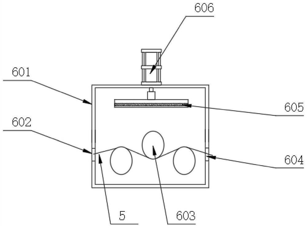
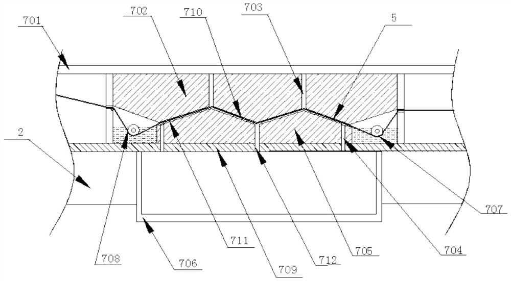
[0025] see Figure 1~4 , in an embodiment of the present invention, a carbon fiber composite material melt impregnation equipment for automobiles, which includes an upper impregnation mold base 702 and a lower impregnation mold base 705, and the upper and lower impregnation mold bases 702 and the lower impregnation mold base 705 are arranged to be buckled up and down , and the upper impregnation mold base and the lower impregnation mold base are sequentially provided with a pre-impregnation chamber 708, a longitudinal impregnation chamber 7 and a final impregnation chamber 707, wherein the carbon fiber composite material 5 to be impregnated passes through the Prepreg chamber 708, vertical impregnation chamber 7 and final impregnation chamber 707; the viscosity of the melt in the prepreg chamber 708 is greater than the viscosity of the melt in the final impregnation chamber 707; and the longitudinal impregnation chamber 7 The melt inside can flow along the direction of extensio...


PUM


Abstract

The invention relates to the technical field of carbon fiber material fusion impregnating and discloses carbon fiber composite material fusion impregnating equipment for an automobile. By forming a pre-impregnating cavity, a vertical impregnating cavity and a final impregnating cavity, during impregnating, a to-be-impregnated carbon fiber composite material penetrates through the pre-impregnatingcavity, the vertical impregnating cavity and the final impregnating cavity in sequence, the viscosity of a melt in the pre-impregnating cavity is greater than that of a melt in the final impregnatingcavity, a carbon fiber can be firstly impregnated in the environment with high viscosity and finally impregnated in the environment with low viscosity and good fluidity, the thoroughness degree of impregnating is improved, and the adverse effect caused when the carbon fiber is directly placed in a place at a high temperature is reduced. According to the equipment, the melt in the vertical impregnating cavity can flow in the extension direction of the composite material, flowing is conducted in the extension direction of the composite material for impacting impregnating, the multi-directional performance of impregnating is improved, and the impregnating thoroughness is guaranteed.

Description

technical field [0001] The invention relates to the technical field of melting and impregnation of carbon fiber materials, in particular to equipment for melting and impregnating carbon fiber composite materials for automobiles. Background technique [0002] Carbon fiber composite material is a composite material in which different carbon fibers are combined by adding thermoplastic resin to reinforce fibers in one direction and continuously. During the manufacturing process of carbon fiber composite materials, impregnation is required, but at present, pre-dispersion is required before impregnation, and carbon fibers are spread into monofilament fibers. At present, when impregnating carbon fiber composite materials, impregnation chambers with wave shapes or other structures are generally used impregnation, although this impregnation method is simple, but the impregnation effect is general, the impregnation of carbon fiber and molten material, such as molten resin, etc. is not...

Claims


Application Information

Patent Timeline
Patent Type & Authority Patents(China)
IPC IPC(8): B29C70/50B29C70/54
CPCB29C70/50B29C70/54
Inventor 赵宏旺
Owner GUILIN UNIV OF AEROSPACE TECH
Learn More