PCB conveying module and conveying device

A PCB board and module technology, applied in the field of circuit board feeding equipment, can solve the problems of circuit boards cannot be fixed, circuit boards are pressed, circuit boards are damaged, etc.

Pending Publication Date: 2019-11-01
ZHUHAI ZHIXIN AUTOMATIC TECH CO LTD
View PDF0 Cites 2 Cited by
  • Summary
  • Abstract
  • Description
  • Claims
  • Application Information

AI Technical Summary

Problems solved by technology

However, due to the need for space movement, the loading and unloading manipulator leads to a large footprint of the entire equipment. During use, the loading and unloading manipulator easily interferes with the movement of the plug-in head components on the plug-in machine, and the loading and unloading manipulator performs adsorption or clamps the circuit board. , easy to cause damage to the circuit board
[0003] For this reason, some enterprises have designed pipeline-type conveying devices to solve such problems. Most of the conveying devices use belts for conveying. The lack of the function of fixing and limiting the circuit board makes the plug-in head part prone to inaccurate plug-in and crooked plug-in when plugging in the circuit board on the conveying device
For the above problems, the conveying devices commonly used in the market currently only limit the position of the circuit board on the conveying device through a simple limit structure, that is, mainly restrict the circuit board to be located on both sides of the conveying direction of the conveying device, because the conveying device itself has Certain flexibility, so when the plug-in head part inserts the circuit board, the circuit board is still easy to transmit the force on the plug-in to the conveying device
The conveying device will transmit the reaction force to the circuit board after being deformed by force, and the existing limit structure only simply limits the two sides of the circuit board, and does not compress the circuit board, so the circuit board cannot be fixed in the plug-in process. , the accuracy of the plug-in is difficult to guarantee

Method used


Image

  • PCB conveying module and conveying device
  • PCB conveying module and conveying device
  • PCB conveying module and conveying device

Examples


Embodiment Construction

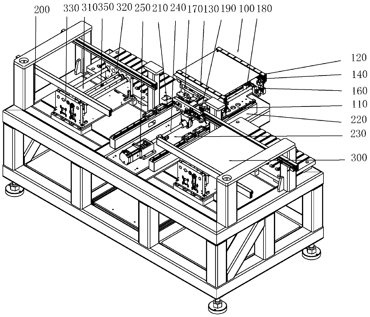
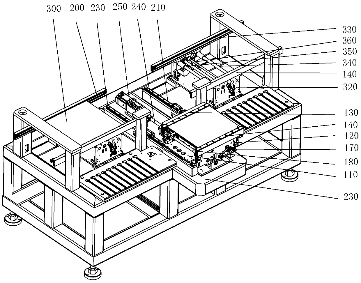
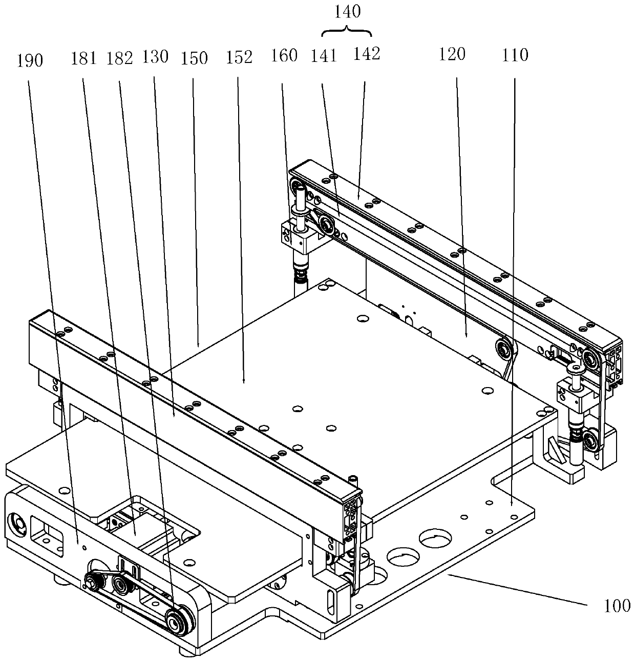
[0027] see Figure 1 to Figure 8 , the present invention also provides a conveying device, including a frame 200 and a conveying module 100; a slide rail 210 is provided on the frame 200, and the conveying module 100 is slidably installed on the slide rail 210, and the frame 200 Both sides of the slide rail 210 are provided with feeding and discharging mechanisms 300; when the conveying module 100 slides on the sliding rail 210 to the corresponding positions of the feeding and discharging mechanisms 300 on both sides, the feeding and discharging mechanisms 300 on both sides can be respectively connected to the conveying module 100 inlet and outlet. It should be noted that in this embodiment, the feeding and discharging mechanism 300 is symmetrically arranged on both sides of the slide rail 210, and the conveying directions of the two groups of feeding and discharging mechanisms 300 are collinear, while the conveying module 100 and the two groups of feeding and discharging mech...


PUM


Abstract

The invention discloses a PCB conveying module. The module involves a sliding seat, a lifting mechanism and a conveying mechanism, wherein the conveying mechanism is arranged on the sliding seat and comprises a fixed vertical plate and a movable vertical plate, the fixed vertical plate and the movable vertical plate can be far away from or close to each other, clamping conveying channels used forclamping and conveying the edges of the two sides of a work piece are arranged on the opposite sides of the fixed vertical plate and the movable vertical plate, and the lifting mechanism is arranged on the sliding seat and used for jacking the work piece. The invention further discloses a conveying device. According to the conveying module, the clamping and conveying channels are used for clampingand conveying the edges of the two sides of the circuit board, so that the abrasion is small in the conveying process of the whole circuit board; the lifting mechanism is used for lifting the whole circuit board through floating jacking heads, so that the whole circuit board can be separated from the whole clamping and conveying channels, and the reaction force of the clamping and conveying channels on the circuit board during external part inserting is avoided; and due to the floating design of the jacking heads, all the jacking heads can be ensured to be in good contact with the circuit board, and the problem of insufficient support of the local circuit board is avoided.

Description

technical field [0001] The invention relates to the technical field of circuit board feeding equipment, in particular to a feeding device. Background technique [0002] A plug-in machine is a machine that inserts electronic components into a designated position on a circuit board. Usually, in order to realize automatic loading and unloading, the plug-in machine is generally equipped with a loading and unloading robot. However, due to the need for space movement, the loading and unloading manipulator leads to a large footprint of the entire equipment. During use, the loading and unloading manipulator easily interferes with the movement of the plug-in head components on the plug-in machine, and the loading and unloading manipulator performs adsorption or clamps the circuit board. , easy to cause damage to the circuit board. [0003] For this reason, some enterprises have designed pipeline-type conveying devices to solve such problems. Most of the conveying devices use belts f...

Claims


Application Information

Patent Timeline
Patent Type & Authority Applications(China)
IPC IPC(8): B65G15/58B65G47/34
CPCB65G15/58B65G47/34
Inventor 李宝生范秀广蒋兴峰冯艳生罗建明李天玉张凡林锡宁严炜林森明
Owner ZHUHAI ZHIXIN AUTOMATIC TECH CO LTD
Why Eureka
Try Eureka