Rounded glass cutting machine

A cutting machine and glass technology, applied in glass cutting devices, glass manufacturing equipment, manufacturing tools, etc., can solve the problems of high labor consumption and poor safety, achieve convenient operation, improve safety, and reduce accidental scratches the effect of risk

Active Publication Date: 2019-11-01
威海烟华安全玻璃有限公司
View PDF5 Cites 12 Cited by
  • Summary
  • Abstract
  • Description
  • Claims
  • Application Information

AI Technical Summary

Problems solved by technology

[0003] In order to overcome the disadvantages that manual cutting is prone to large errors, requires a large amount of manpower, and has poor safety, the technical problem of the present invention is to provide a circular cutting machine that can accurately perform circular cutting, save manpower, and have high safety. glass cutting machine

Method used


Image

  • Rounded glass cutting machine
  • Rounded glass cutting machine
  • Rounded glass cutting machine

Examples


Embodiment 1

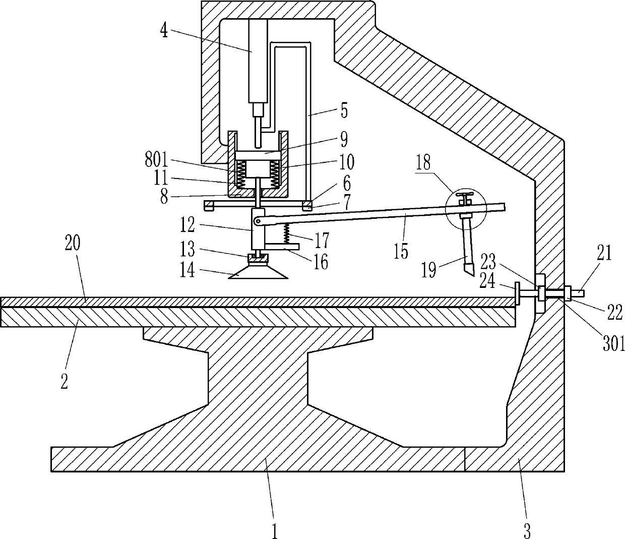
[0019] A round glass cutting machine such as Figure 1-2 As shown, it includes a base 1, a platform 2, a frame 3, a first cylinder 4, an N-shaped rod 5, an iron ring 6, a pressing block 7, a U-shaped frame 8, a first mounting plate 9, a motor 10, a first Spring 11, connecting plate 12, bearing seat 13, rubber pressure plate 14, scale rod 15, horizontal plate 16, second spring 17, adjustment mechanism 18 and glass cutter 19, platform 2 is connected to the upper part of base 1, and base 1 passes through The way of welding connection is connected with the platform 2, the lower part of the right side of the base 1 is connected with the frame 3, the first cylinder 4 is installed on the top of the inner side of the frame 3, and the telescopic rod of the first cylinder 4 is connected with the N-shaped rod 5. 3. A U-shaped frame 8 is connected to the lower part of the inner left side. The inner wall of the U-shaped frame 8 has a chute 801. The U-shaped frame 8 is slidably connected to...

Embodiment 2

[0021] A round glass cutting machine such as Figure 1-2 As shown, it includes a base 1, a platform 2, a frame 3, a first cylinder 4, an N-shaped rod 5, an iron ring 6, a pressing block 7, a U-shaped frame 8, a first mounting plate 9, a motor 10, a first Spring 11, connecting plate 12, bearing seat 13, rubber pressure plate 14, scale rod 15, horizontal plate 16, second spring 17, adjustment mechanism 18 and glass knife 19, platform 2 is connected to the upper part of base 1, base 1 right The lower part of the side is connected with a frame 3, the top of the inside of the frame 3 is equipped with a first cylinder 4, the telescopic rod of the first cylinder 4 is connected with an N-shaped rod 5, and the lower left side of the frame 3 is connected with a U-shaped frame 8. The inner wall of the type frame 8 has a chute 801, and the U-shaped frame 8 is slidingly connected with a first mounting plate 9, the first mounting plate 9 is matched with the chute 801, and a motor 10 is inst...

Embodiment 3

[0024] A round glass cutting machine such as Figure 1-2 As shown, it includes a base 1, a platform 2, a frame 3, a first cylinder 4, an N-shaped rod 5, an iron ring 6, a pressing block 7, a U-shaped frame 8, a first mounting plate 9, a motor 10, a first Spring 11, connecting plate 12, bearing seat 13, rubber pressure plate 14, scale rod 15, horizontal plate 16, second spring 17, adjustment mechanism 18 and glass knife 19, platform 2 is connected to the upper part of base 1, base 1 right The lower part of the side is connected with a frame 3, the top of the inside of the frame 3 is equipped with a first cylinder 4, the telescopic rod of the first cylinder 4 is connected with an N-shaped rod 5, and the lower left side of the frame 3 is connected with a U-shaped frame 8. The inner wall of the type frame 8 has a chute 801, and the U-shaped frame 8 is slidingly connected with a first mounting plate 9, the first mounting plate 9 is matched with the chute 801, and a motor 10 is inst...


PUM


Abstract

The invention relates to a glass cutting machine, in particular to a rounded glass cutting machine. The rounded glass cutting machine can accurately conduct round cutting, saves manpower and is high in safety. The rounded glass cutting machine comprises a base, a platform, a rack, a first air cylinder, an N-shaped rod, an iron ring, a pressing block, a U-shaped frame, a first mounting plate, a motor, a first spring, a connecting plate and the like. The upper part of the base is connected with a platform; the right lower part of the base is connected with a rack; a first cylinder is mounted atthe top inside the rack. The rounded glass cutting machine is provided with the adjusting mechanism and the glass cutter, the position of the glass cutter is adjusted through the adjusting mechanism,rounded glass of a certain size can be accurately cut, and the accurate cutting effect is achieved; meanwhile, the motor arranged on the rounded glass cutting machine drives the glass cutter to rotatethrough related parts to conduct round cutting, and operation is convenient; the rounded glass cutting machine is further provided with a material box and related components, so that the equipment can move glass blanks more conveniently.

Description

technical field [0001] The invention relates to a glass cutting machine, in particular to a round glass cutting machine. Background technique [0002] People usually change the shape of glass through processing and modify it, and then use it in people's daily life. In the process of processing, people usually use tools for manual cutting, and sometimes people need to cut the glass into a circle, but manual cutting is prone to large errors, and it is also quite inconvenient to operate on glass blanks with a large area; in addition, The glass embryos that need to be cut and processed are usually large in size and quite heavy. When handling the glass embryos, they are easy to bump and cause damage, which not only brings losses, but also may scratch the hands of the processor, which is poor in safety. Contents of the invention [0003] In order to overcome the disadvantages that manual cutting is prone to large errors, requires a large amount of manpower, and has poor safety,...

Claims


Application Information

Patent Timeline
Patent Type & Authority Applications(China)
IPC IPC(8): C03B33/04
CPCC03B33/04
Inventor 李玲玲
Owner 威海烟华安全玻璃有限公司
Why Eureka
Try Eureka